Continue to Site

Welcome to our site!

Electro Tech is an online community (with over 170,000 members) who enjoy talking about and building electronic circuits, projects and gadgets. To participate you need to register. Registration is free. Click here to register now.

  • Welcome to our site! Electro Tech is an online community (with over 170,000 members) who enjoy talking about and building electronic circuits, projects and gadgets. To participate you need to register. Registration is free. Click here to register now.

Car Battery Charger

Status
Not open for further replies.

Ricky

New Member
Hello there,

Can anyone provide a schematic/s for a battery charger for at least 6 ampere or more current out and with an indicator if it is already full
charge and for 12 volts system and any info on any adjustment necessary. :)
 
Look at:

**broken link removed**

It's good for 3A, but you can increase it to 6A by paralleling 2 LM350s, or adding a pass transistor to the regulator.
 
Phasor,

Is there a way to increase the ampere rating of that charger?
Or what component should be change so as to get at least 6 amp or more output? Thanks for the reply. :eek:
 
For up to 6A, you can do as I mentioned above - parallel 2 LM350's. Or you can add a pass transistor as shown - I haven't drawn the whole circuit, just the first bit:
(For the transistor, I would use a 2N2955 or similar, mounted on a generous heatsink)

Also, I can't see the purpose of R1 - I would delete it.
 

Attachments

  • BattCharge.jpg
    BattCharge.jpg
    15.6 KB · Views: 1,649
As I see it is a current boosted circuit right? Maybe I can use the cheaper LM 317 regulator instead of the 350 ? could be that the R1 might be for trickle charge purpose ,just a guess :lol:
 
Series Pass Circuit

Phasor Is there an error on your diagram that if the load takes 1/2 amp the pass transistor will turn hard on allowing the 18v input through to the battery (which will not rise to this voltage).
The circuit will latch up with no voltage regulation.

I think the linked circuit has to have R1 to start the circuit up - providing some signal through to the control circuitry, otherwise I think the regulator would remain 'shut down' as if the battery was fully charged.
 
Maybe I can use the cheaper LM 317 regulator instead of the 350

Yes, that should be OK.

the pass transistor will turn hard on
Why would it do that?

I think the linked circuit has to have R1 to start the circuit up

I didn't think of that... :oops:
A little research shows that this circuit was actually copied directly from the National Semiconductor LM350 datasheet. (NB - It does include R1 on the datasheet, so I guess it should be there after all...)
 
No problem with circuit. Pass transistor can't go latch-up,because if output go higher, LM317 sense it and decreasing own input current, decreasing opening voltage of bypass transistor (on R1)
 
Oops

Sebi - Yes, you are correct, it will regulate OK

Sorry - shallow thinking again - brain-ache! - Need more beer!
 
So guys do I need to use the R1 in the circuit?


Phasor
What is the function of that 2.2 ohms/2w resistor in the circuit?
If I increase or decrease the value what will be the consequenses?
:eek:
 
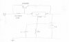
R1 along with R2 sets the output voltage.......R1 is nominally 240 ohms....making R2 adjustable sets the output..........

The purpose of the 2R2 resistor is as follows :

Consider the output voltage as 13.8v, as the load current increases, the o/p volts drop, the reg makes up the difference in v out, the circuit then becomes stable. Now as the load current increases the voltage across the 2R2 resistor (R3 for arguments sake) rises, as V=I*R,

Now Vbe of Tr1 is ~ 0.6v, so if R3 is 2R2 and the load current rises such that it develops a voltage across it of 2R2*I volts, then as it approaches Vbe of Tr1, Tr1 will start to conduct, causing a rise in o/p volts, the reg cuts back its o/p and so the current falls, eventually the system restabilises.......

The value of R3 isnt critical it sets the point of operation of Tr1, the higher the value of R1 the more current is passed by the regulator until Tr1 turns......the ideal situation would be to allow a nominal current through the regulator to enable it to perform, and the remainder of the current supplied by Tr1........

Hope this explains it all 8)
 
thanks for all you reply.

final design will be using two pass transistor ( mj2955 ) for more reliabilty and a big chunk of heatsink.
 
Status
Not open for further replies.

Latest threads

New Articles From Microcontroller Tips

Back
Top