Hi all, I hope I am posting this into the correct forum. I am a newbie in electronics so I want few advises and suggestions on how to do that thing correctly.
I got an old broken car battery charger from my neighbour and I want to make it go again and possibily modifiy ti to be a better one.
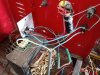
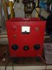
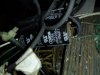
Here is a picture of it and of its internals, the circuit is very simple and I think I understand it well, but there are still some things i can not
understand well. So lets go by the design and doubts.


The circuit itself is composed from a transformer, which has different windings yo get out different voltages. These goes connected to a switch for voltage selection, then they go to the rectifier bridges, from there there are 2 electrolitic condensers and from there they flow goes to the battery leads, the negative going directly to the negative of the battery and the positive passes through an AM meter then a fuse and then to the positive battery lead.
Here is a schematic of the whole circuit. Originally probably this went to some more switches, which i dont know why.
Schematic
**broken link removed**

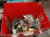
Here is the photo of the capacitors and their values are 4700uF and 1500uF , if i get it correctly since they are in paralel we can
consider it as one cap of 6200uF , correct ?

One first thing is that I have no idea on why the primary winding of the transformer has another one which divides the main voltage from 128V and give the voltage of 65V , why does it need that ?
The other thing I do not get is why there are 2 rectifier bridges ? BR1 and BR2 are KBPC5010 .

The third thing is that when I rewire it and make the measurement with the capacitors connected the voltage started up to grow and grow.
Lastly I want to know if I choose the correct voltage output from the transformer. The transformer has a lot of output windings rangeing from 0V up to 32V
from what i could measure. I choose the 2 wires which showed on 17,70V. Is that tyoo high for a 12V car or truck battery ?
Will I be able to charge the truck battery with it which has the capacity of 110Ah ?
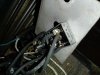
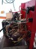
Here is a picture of how it is right now rewired.
I also plan to insert in a new AM meter as the old one was broken, and possibly also an additional Volt meter. Probably digital ones, opinions ?
Many thanks for your help.
Sasa
I got an old broken car battery charger from my neighbour and I want to make it go again and possibily modifiy ti to be a better one.
Here is a picture of it and of its internals, the circuit is very simple and I think I understand it well, but there are still some things i can not
understand well. So lets go by the design and doubts.
The circuit itself is composed from a transformer, which has different windings yo get out different voltages. These goes connected to a switch for voltage selection, then they go to the rectifier bridges, from there there are 2 electrolitic condensers and from there they flow goes to the battery leads, the negative going directly to the negative of the battery and the positive passes through an AM meter then a fuse and then to the positive battery lead.
Here is a schematic of the whole circuit. Originally probably this went to some more switches, which i dont know why.
Schematic
**broken link removed**
Here is the photo of the capacitors and their values are 4700uF and 1500uF , if i get it correctly since they are in paralel we can
consider it as one cap of 6200uF , correct ?
One first thing is that I have no idea on why the primary winding of the transformer has another one which divides the main voltage from 128V and give the voltage of 65V , why does it need that ?
The other thing I do not get is why there are 2 rectifier bridges ? BR1 and BR2 are KBPC5010 .
The third thing is that when I rewire it and make the measurement with the capacitors connected the voltage started up to grow and grow.
Lastly I want to know if I choose the correct voltage output from the transformer. The transformer has a lot of output windings rangeing from 0V up to 32V
from what i could measure. I choose the 2 wires which showed on 17,70V. Is that tyoo high for a 12V car or truck battery ?
Will I be able to charge the truck battery with it which has the capacity of 110Ah ?
Here is a picture of how it is right now rewired.
I also plan to insert in a new AM meter as the old one was broken, and possibly also an additional Volt meter. Probably digital ones, opinions ?
Many thanks for your help.
Sasa
Attachments
-
 car_battery_charger.jpg142.1 KB · Views: 481
 -
 car_battery_charger.jpg142.1 KB · Views: 434
 -
 car_battery_charger_top.jpg196 KB · Views: 461
 -
 bridge_rectifier.jpg174.2 KB · Views: 489
 -
 capacitors.jpg156.4 KB · Views: 444
 -
 circuit.png20.1 KB · Views: 442
 -
 internals_before_rewireing.jpg158.5 KB · Views: 461
 -
 rewired_full.jpg199.4 KB · Views: 488
Last edited:
