Continue to Site

Welcome to our site!

Electro Tech is an online community (with over 170,000 members) who enjoy talking about and building electronic circuits, projects and gadgets. To participate you need to register. Registration is free. Click here to register now.

  • Welcome to our site! Electro Tech is an online community (with over 170,000 members) who enjoy talking about and building electronic circuits, projects and gadgets. To participate you need to register. Registration is free. Click here to register now.

Capatitive Discharge Ignition technical discussion

Status
Not open for further replies.

monette999

New Member
Dear All,

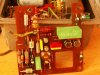
I have received an old vintage Capatitive Discharge Ignition from Bosch of an NSU R0 80.

The people who design this unti are already retired and I am having hard time
to analyse the schematic.

The system has signal conditioning
DC/DC converter and a discharge cuircuit.

The self occilating part is very complex. I am trying to find out how can I test the unit is dissambled system.

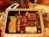
I have upper board with is the rev limiter spark disable & fuel cut-off.
The lower part is the ignition unit. Currently it is not working. My power supply goes in current limiting at 3A. It takes more the 3amps.

how does the cuircuit start to swing in?
Over the points of itself with the 12V supply. That is not clear to me.

Best Regard
Bob

Thank you for your participation
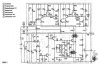

Here the schematic?
 

Attachments

  • HKZ11189320664.jpg
    HKZ11189320664.jpg
    59.9 KB · Views: 857
  • IMGP4215.JPG
    IMGP4215.JPG
    68.5 KB · Views: 498
  • IMGP4220.JPG
    IMGP4220.JPG
    58.3 KB · Views: 573
hi,
To check the EHT section.
Charge C8 upto say 24V, using the junction of C8 and D10 as the charge point.
[Whats the voltage rating of C8?]

Trigger the Thy2 by injecting a +5V pulse into the junction of D7 and R17.
This should trigger the Thy2 to discharge C8 thru the 'A' primary coil, giving a HV pulse at '2'.
Use an old spark plug as a test spark gap, set the gap initially to 10thou and open it to 20thou if you get a spark.

OK.


Hello Eric,
the C8 is 1.4 mF 600V. Thank you, but I am intersted how the occilation works. Does the box starts occilating when you supply 12V or first when the trigger is activated (points)

BR
Bob
 
The oscillator runs while the points are closed, as the points open the oscillator is stopped briefly, the thyristor is triggered, and C8 is discharged through the ignition coil. As soon as the points close again, the oscillator restarts.
 
hi,
Nigel got in first this time.:D I must be slowing down.!

I would test the final Thr2, make sure its not blown.
 
Last edited:
Age getting to you Eric :p

I need I little toning up, we must get on the mat again soon.!;)

If I was the OP I would designate this unit to the pending a 'rainy day' box.
 
Last edited:
The oscillator runs while the points are closed, as the points open the oscillator is stopped briefly, the thyristor is triggered, and C8 is discharged through the ignition coil. As soon as the points close again, the oscillator restarts.

Hello Nigel, thank you for taking the time to reply on my thread. I really apresciate your help. I was asking some Bosch people but the developers of this unit are already retired.

What would you use for the replacement of the RGV 527 & RTD0410 Thyristors. Bosch coded the parts.


My box does not occilate properly. If I supply my box with my power supply it will go in current limitation at 3 ampere. The voltage is 5V with the chopped current.

When I now simulate the points the box starts oscillating.
now when I hook the same unit to a battery I can't get the unit occilating.

It locks up and does not oscillate.

The two big diodes and thy power thyristor are (were) bad ( now replaced)

D9, D10 and Thy2 on the schematic.
Do I have a short in the secondary winding. I heard some unusual noise when I run a test. after the test the 2N2905A TR2 was bad.
I replaced it.

How can I test the transformer?

BR

Bob


How would you test a disassembled unit.


Best regards,

Bob
 
Last edited:
Hello Nigel, thank you for taking the time to reply on my thread. I really apresciate your help. I was asking some Bosch people but the developers of this unit are already retired.

What would you use for the replacement of the RGV 527 & RTD0410 Thyristors. Bosch coded the parts.


My box does not occilate properly. If I supply my box with my power supply it will go in current limitation at 3 ampere. The voltage is 5V with the chopped current.

When I now simulate the points the box starts oscillating.
now when I hook the same unit to a battery I can't get the unit occilating.

It locks up and does not oscillate.

The two big diodes and thy power thyristor are bad

D9, D10 and Thy2 on the schematic.
Do I have a short in the secondary winding. I heard some unusual noise when I run a test. after the test the 2N2905A TR2 was bad.
I replaced it.

How can I test the transformer?

You can use a technique called 'ringing', essentially applying a pulse, and monitoring the back EMF pulses using a scope. You can buy cheap kits to test LOPTX's, which display on a row of LED's (actually counting the number of 'rings').

How would you test a disassembled unit.

With a battery, an ignition coil, spark plug, and a switch to simulate the points.
 
You can use a technique called 'ringing', essentially applying a pulse, and monitoring the back EMF pulses using a scope. You can buy cheap kits to test LOPTX's, which display on a row of LED's (actually counting the number of 'rings').


With a battery, an ignition coil, spark plug, and a switch to simulate the points.

That is excactly what I am doing but with 12V battery supply it won't start oscillating. I press the trigger and (using a switch) but oscillating won't start.

Do you know how the flyback cuircut works. The T2 is creating a phase shift and pulsing back the base. I assume that cuircut is bad.

When I test the unit I saw a high current( more than 3 amps) may the T3 is not closing properly. Then I saw a DC Voltage of 0.8V on the base of
T3 with no trigger.

I am still searching where it could came from. Maybe T2 DC offset Voltage


I will make some snapshots.

BR
Bob
 
Last edited:
Hello
attached the picture of the Base of TR3.
The 1.4V is opening partly the C & Emitter current.

Here the signal A without the TR3 & T2. 1.42V with a limited time of high level.

BR
bob
 

Attachments

  • Base TR3 with Trigger by func generator.jpg
    Base TR3 with Trigger by func generator.jpg
    53.1 KB · Views: 226
  • Base TR3  Gate Thy2.jpg
    Base TR3 Gate Thy2.jpg
    61.3 KB · Views: 179
Status
Not open for further replies.

Latest threads

New Articles From Microcontroller Tips

Back
Top