Just a little FYI, I have a DeLorme PN60 GPS that's about 5 years old, DeLorme is now owned by Garmin, and while it still works well, I keep having battery problems. I had MiMH batteries in it, but always forgot to put freshly charged ones in and it would drop out, probably due to momentary power connection loss, and I wouldn't notice for a while, So I would lose that part of the track. Because of my handicap, I never take it anywhere by foot, just in my Trooper. It will run for about a (minute)(to be edited) on the super caps now. The connection to USB cord has been modified also because the unique original became expensive to replace. Seems to be doing well now!
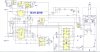
Spec, I think it was you that said something about having a resistor in the gate for FETS , on my power steering project's H bridge, I PWM the NFET (IRF2805) via a NE556 and 100Ω in parallel with a diode and just turn on it's complement PFET (IRF4905) via a 510Ω resistor, would you care to make any comments or suggestions?
Thanks,
Jeff
")
 but i'm thinking you want a more detailed theory of operation, I'm putting together a zip file with all you'll need.