Electro Tech is an online community (with over 170,000 members) who enjoy talking about and building electronic circuits, projects and gadgets. To participate you need to register. Registration is free. Click here to register now.
Welcome to our site! Electro Tech is an online community (with over 170,000 members) who enjoy talking about and building electronic circuits, projects and gadgets. To participate you need to register. Registration is free. Click here to register now.
Are you taking about a smoothing capacitor or a capacitive ballast?
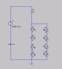
For a capacitive ballast, connect the LEDs as two series pairs wired in reverse parallel and use a 150R resistor and a 33µF capacitor to limit the current. Note that the capacitor needs to be bipolar, an standard electrolytic is no good.
There's no of course about it, here's another way of doing it without a bridge rectifier.
If you go for the bridge rectifier option, you don't even need a smoothing capacitor. If you want to get rid of the flicker then a 220µF capacitor will well and truly squash the ripple to below 2V.
Note that all resistor calculations should assume the output from the rectifier to be 15V.
On behalf of flicker sensitive people everywhere if you use a bridge rectifier PLEASE use a filter cap =) I made an LED bank once that ran off AC power and the flicker was pretty bad.
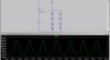
Sounds like you need to use a bigger resistor. Just watch for the power dissipation in the resistor as well. Also make sure the voltage charactoristics of the LED's you're using in the simulator match your real diodes.
It depends on the forward voltage drop across the diodes.
What's the Vf of the diodes in the simulation?
I went on the fact that white LEDs have a forward voltage of about 3.5V, four in series makes 14V. (17-14)/47 = 63.8mA and the LEDs will only be conducting every half cycle for less than half a cycle, giving an average current of much less.
This site uses cookies to help personalise content, tailor your experience and to keep you logged in if you register.
By continuing to use this site, you are consenting to our use of cookies.

")