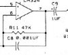
There are quite a few different schematic symbols for capacitors, some geographically mandated (Euro cap symbols differ or have differed from U.S. symbols), some according to year, others according to company drawing standards. In 1944, caps were drawn as two straight lines. The curve of one plate appeared during the late 1950s, early 1960s. The curved side usually meant negative lead for electrolytics or "outside foil" for axial-lead paper or plastic dielectric caps.
The smallest electrolytic (polarized) capacitor that I recall seeing is a little 0.47µF (and there may have been a 0.1µF) tantalum that I have in my stock. If you compare the same value electrolytic against a non-polarized version, you'll find a LOT less series inductance and ESR on the electrolytic, which could be critical in some applications.

")
