Continue to Site

Welcome to our site!

Electro Tech is an online community (with over 170,000 members) who enjoy talking about and building electronic circuits, projects and gadgets. To participate you need to register. Registration is free. Click here to register now.

  • Welcome to our site! Electro Tech is an online community (with over 170,000 members) who enjoy talking about and building electronic circuits, projects and gadgets. To participate you need to register. Registration is free. Click here to register now.

Capacitor popped even after voltage rrquirements met

Status
Not open for further replies.

mik3ca

Member
I made a major circuit which can run nicely with a 9V battery. After measuring the current with everything on, it turns out about 250mA is used.

I then created a charger similar to this one except I replaced everything before C1 with a 12VDC/800mA wall wart. I also used 1.5K resistor instead of a pot and adjusted other parts accordingly.

Portable-Automatic%2BCircuit-Diagram-of-Automatic-Battery-Charger.jpg


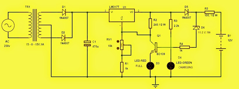
This is what was confusing. my Capacitor C1 was 22uF and rated for 50V. Its about 5mm in size and has a label WH105 degrees. I then ran a test. I powered the circuit via the wall wart and I was about ready to measure the output areato make sure the voltage was right for my needs. About 5 seconds after the unit was turned on, capacitor C1 immediately popped. At first I thought I damaged the entire circuit, but instead, the entire can flew off (with the exception of the connecting leads) and a sprinkle of light grey was scattered in the area. It turned out to be feathery in nature.

So why would such a capacitor blow up when its voltage rating is significantly higher than the input voltage?
 
What Ron said,
and,
are you sure the wall wart was outputting DC and not AC ?

JimB
 
Too much ripple current.

The capacitor has to support the output load for 1/120 s with 60 Hz mains. At 250 mA that is about 2 mC (milli Coulombs). The 470 μF capacitor is too small because it will have 0.002 / 0.00047 ≈ 4 V of ripple, but it will sort of work. A 22 μF capacitor will be completely discharged each half cycle and will get too hot from the rate of charge and its internal resistance.

You need a much larger capacitor to handle that duty.

Even if your wall wart has it's own smoothing, that won't be perfect and a 22 μF capacitor isn't rated for much ripple at all.

https://products.nichicon.co.jp/en/pdf/XJA043/e-pw.pdf

Nichicon say 170 mA at 100 kHz, 51 mA at 120 Hz

If your regulator is oscillating, you could get a lot more ripple current than you thought.
 
Oh. The thing thats weird is that on my other circuit, I use the same style 22uF capacitor across the input of an LM2940 regulator and hooked that to a 9V battery and that capacitor didn't blow up. I guess these wall power supplies like to create ripple then? Is there some equation I can follow to calculate the minimum capacitor value necessary to prevent blow-up?
 
Are the wall warts different? Can you post photos?

Wall warts can have conventional transformers, which are quite large and heavy, and the input voltage will be just 110 / 120 or 220 / 240 V. They will never handle a wide voltage range unless there is a switch to change the voltage.

Wall warts with conventional transformers can have:-
AC output.
DC output, unsmoothed
DC output, smoothed
DC output, smoothed and regulated.

Alternatively, wall warts can have high frequency transformers, which are small and light, and usually the input voltage covers a wide range, such as 100 - 240 V. They always have a DC output, smoothed and regulated, but the quality of that smoothing and regulation can vary.

You regulator may need a minimum capacitance on its input to stop it oscillating.

Capacitor selection can get very involved, and so a simple equation risks being an over-simplification. As a guide, 10,000 μF per amp of load is a good start. You may be able to go smaller with more careful consideration.
 
I wasn't using two different wall warts. I was only using one for the charger section of my circuit and the capacitor right where the wall wart connects blew up.
In the other circuit with a regulator, I used a 9V battery.
 
In the other circuit with a regulator, I used a 9V battery.
A 9V battery (PP9 type) has a fairly high internal resistance, which would have limited the current drawn by the capacitor charging.
 
I thought about ripple current but:
1) The "wall wort" probably has 470uF or 1000uF inside. Little ripple current in C1
2) The load is a battery with 100 ohms in series. R5 So the current will be low. (if this is the real circuit)
3) The load is a battery. (C1 = 22uF and none in the transformer) Then there will be ripple on C1. If the load was a resistor there will be much ripple but it is a battery. As soon as the voltage drops to low to charge the battery the current drops to almost zero. In other words, the charger is only supplying current during the peak of the power line and C1 is not supplying current the rest of the time. (little ripple)
upload_2017-10-2_6-16-52.jpeg

Could just be a bad capacitor.
OR over voltage, backwards, too much ripple current, D1 shorted in transformer so AC!!
 
as i got the BD139 is some sort of a weird beast used in conjunction with power zener (those things like relatively much current through them) you likely put nothing through it as - say 1.6 LED + 0.7 E-B +11 Zener = 13.3V (the resistor divider alone would do better)
. . .so if your battery gets "full" you attempt to shut down the 317 ? there would be a lot of heat on R5 or less than 100mA (i speculate) WTH is the B1 ? why to charge it so long . . .

ok , autofix = your LM317T outputs 1.25*2.5k/0.24k=13.0V (but not with 12V input from **broken link removed**) which behind D5 will be (at best) 12.4V ? sort of trickle charger
for PbSO4 would be depending on type and temperature 12.6 13.6 14.2 14.7

there is reverse current path enabled as D6 R4 D(Q1.B-C) - e.g. if your red led fails at above 40mA through it your voltage goes as high as your input allows
. . .
profiling the charger concept (with random voluntary mod.-s)
>> now without known bugs !!
 

Attachments

  • ACA Dummy 15V-2-PbSO4.png
    ACA Dummy 15V-2-PbSO4.png
    55.2 KB · Views: 137
  • ACA Dummy 15V-2-PbSO4 - fix.png
    ACA Dummy 15V-2-PbSO4 - fix.png
    52.1 KB · Views: 133
Last edited:
I'll provide my circuit. The unmarked capacitor at the far left was a 22uF but now its blown. The zener diode with no value marked was not inserted yet because I don't have one to detect 7.2V in my inventory yet so that's an open circuit. Could that have anything to do with it?

Or is my power adapter that bad? I mean before I powered a commercial blacklight with it no problem. I don't know how to tell if a diode in an adapter is blown without spending a day removing the power adapter cover and I'm not about to do that.

But then again, I wonder if the capacitor is the issue. I remembered in the past doing a circuit where a 100uF capacitor (and I think the voltage rating was 25) was across the same adapter, and nothing blew up that time.

Are there any other things I can do to prevent a capacitor from blowing up?

circuitx.png
 
I Suggest you measure the Wall Wart Adapters Output.
Even Better, Look at its output on an Oscilloscope to see AC Ripple.

Some Digital meters can read the AC Ripple on the AC Range.
On AC Range, Some Meters just show the DC Voltage at Twice the DC Voltage.
 
Last edited:
ok I did measure the DC voltage from the wart before the incident happened and it reported 18V which is far less than the 50V the blown cap was rated for.

I'm about ready to throw this adapter away and buy a new one, but when I measure ac coming from the adapter, what number am I looking for on the meter to indicate whether the 22uF/50V capacitor I'm about to connect to it is likely to blow up or not?
 
Ideally the DC out should be JUST DC.
But AC Ripple should be LOW, Probably Less than 1 Volt.

With Ripple Less than 1 or 2 Volts, Unless you connect the Capacitor Backwards it should NEVER get Hot or Explode.
 
Status
Not open for further replies.

Latest threads

New Articles From Microcontroller Tips

Back
Top