A strange phenomenon I witnessed
A while back I had assembled a power supply that put out about 500 volts. I assume you mean 500 Volt RMS.
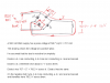
I built a bridge rectifier out of four 1000 volt 6 amp diodes.
The amperage output of the transformer was only about 200mA, which is
well below the 6 amp rating of the the diodes.
Also the 500 volt output of the transformer is only half the 1000 volt rating, of the diodes. I also used a 40 watt lightbulb in series between the transformer, and the rectifiers, just in case I shorted the leads by accident.
While I used two 470mfd capacitors connected in series across the output, all worked well.
I used this setup for hours on end without the diodes even getting warm.
I made 2 homemade capacitors out of Al foil and plastic tarp,
they measured about 300mfd each on the capacitance meter.
I then tried connecting one homemade capacitor in series with a 100 watt light bulb, across the bridge output.
As soon as I powered up the circuit, the capacitor began to shrink because
of the static charge buildup. and then all 4 diodes zapped out.
I say zapped out, because they were still cold to the touch when I checked them.
So this indicated the voltage of the diodes was exceeded and not the amperage.
I made another bridge out of 4 new diodes and tried using the other homemade cap.
Same thing happened again. When I checked the caps on the meter they
still measured about 300mfd so I knew they hadn't shorted out internally.
My understanding is when four 1000 volt diodes are connected as a
bridge rectifier, the bridge should handle 2000 volts because two diodes are
always connected in series at any given time in the circuit. Wrong!
So how did the homemade capacitor build up a charge greater then 2000 volts, from a 500 volt input.
Plus the fact that the 100 watt light bulb in series with it would divide the voltage up some more.
This strange phenomenon is what lead me to believe that the voltage increases when the charged plates of a capacitor
are brought closer together. This didn't just happen once, but twice.
I have no other explanation for what happened to the diodes. Good thing I got them for 17 cents each.
I was so upset with those capacitors I ripped them apart and threw them in the garbage.
But I haven't been able to forget about this mystery since, that is why I started this thread.
I had also wondered if this had something to do with the casimir effect.