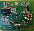
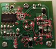
Ok, in this image you can already see how the 5V is generated with an input voltage of 11V. I thought the input voltage was 230V, but I wondered: what if the toaster is inductive and not resistive? So, it may be that the 11V comes directly from the heating element, taking advantage of the inductor to create a transformer from that! The result is exactly what happens, the 11V is generated using the inductor element of the toaster, working as a kind of transformer, causing the current that passes through the inductor that heats up to generate a voltage in a secondary that is in parallel with the heating element.


") ))
))