Continue to Site

Welcome to our site!

Electro Tech is an online community (with over 170,000 members) who enjoy talking about and building electronic circuits, projects and gadgets. To participate you need to register. Registration is free. Click here to register now.

  • Welcome to our site! Electro Tech is an online community (with over 170,000 members) who enjoy talking about and building electronic circuits, projects and gadgets. To participate you need to register. Registration is free. Click here to register now.

Can't access PIC12F675 with ICD2

Status
Not open for further replies.
Thank you Nigel, I will remember that Sir... I had discovered that jpg is what you needed for better photos' and just assumed it was best for everything...

Regards, Mike

<added>

Nigel, I resaved that image as GIF but the colors got all messed up and garbled... I'll play with it more later and figure it out...
 
Mike said:
Thank you Nigel, I will remember that Sir... I had discovered that jpg is what you needed for better photos' and just assumed it was best for everything...

Many people do, but for diagrams GIF's are far better quality (as they don't lose anything), and usually about 20% of the size of a JPG.

It's always worth trying different formats to see how big each one is!.
 
:shock: Wow!It's just been serveral hours of sleep before I came back in and found so many replies!You guys have been so kind here,Thank you! :)

Jay.slovak said:
What a coincidence! I have been playing with my ICD2 and 16F675 all day today.... I had some strange 0x00 problem too. Then, after I re-read the Datasheet, I realised Swapped VSS and VDD in my design (strange, it's different at 16F628). After that it works like charm... Also check if you are not Overloading PGD $ PGC pins of the ICD2 (eg LEDs...).

Ah..ha.I never worked on 16F628,so I got the Vss and Vdd right initially.No pin is overloaded because the chip was only connected to the programming socket.I think it's about the Vpp.

Nigel Goodwin said:
Alex_rcpilot said:
Many other chips have them,e.g,16F877(A).Why does 675 have such configuration problem while 877 doesn't?I browsed throught the documents but couldn't find issues on default config values.If they're all "1"s,then external RC oscillators are designated for both 877 and 675.Signifying the 675 won't be powered up with internal oscillator running by default.I'm so confused!

The 16F877 doesn't have an internal oscillator, so the problem doesn't arise - there's only a fairly small number of PIC's with internal oscillators.

However, exactly the same problem arises when doing ICSP, and you have to select programming mode before the oscillator can start. I've recently modified WinPicProg to give an optional extra output pin - this pulses briefly at the start of programming, and can be used to RESET the PIC to allow you to select programming mode regardless of the oscillator configuration.

Sorry Nigel.What a shame!I should have been more careful reading the document to notice there's not internal oscillator in 877.You did a great job in modifying your WinPicProg.I wish I could have such a programmer too.However....let's figure out this ICD problem first.Here're some items I still don't understand:
A.What is the default status of 675's osc config bits?If it's INTOSC(100 or 101),why would Microchip do this when it brings a problem?
B.Is it possible to access programming mode with Vpp powered on prior to Vdd?
C.How can we explain this "ICD devices must be clocked (internally on INTOSC or externally on OSC1) and have MCLR high to communicate with the MPLAB ICD 2." found in the MPLAB help file?

Regards,Alex

Mike said:
Alex,

I just successfully programmed a 12F675 on my home-built Serial ICD2 but I included a circuit to effect ICD2 controlled Target VDD switching... I was hoping the ICD2 was smart enough to use "VDD first" and VPP first" methods for placing a target device into high voltage program/verify mode and so far I have not had any problems testing on a couple different devices with INTOSC enabled and MCLR disabled for Input...

I do get an ICD2 warning when I'm about to program this INTOSC/MCLR configuration into a target device but it programs the device fine, reads, verifies, etc., so perhaps this is simply not a valid configuration for In Circuit Debugging?

ICDWarn0033: MPLAB ICD 2 does not support programming this device if both the internal oscillator and internal MCLR are selected. You may continue programming, but you are encouraged to cancel, reconfigure your device, and try again.

Regards, Mike

Thank you,Mike.Especially for the diagram.But is RA1 assigned to intercept the target Vdd control in this way on all ICD devices?I just measured my device.The RA4 pin is the Vdd output controlling pin though it's not applied on my ICD.Its state depends on the power settings in MPLAB.When I set the ICD to power the target board,RA4 goes to constant low state.I thought it could be smarter regarding the chip selection,i.e,generate a Vdd first(precise timing prior to Vpp)sequence specially for chips like 12F675.Disappointing however.And the RA1 is in high impedance state.I wonder if you have done anything to the firmware to take advantage of RA1.BTW,how can I cunstomize my MPLAB 7.11 appearance?I didn't find any related setting item here. :?

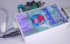
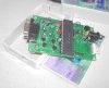
Jay,I love your ICD clone!Fairly good job.I'll try uploading a picture of mine later.I use a wall wart to power the device instead of a home made 5V supply :) 
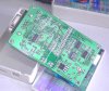
The Vdd output sucks on this ICD.I don't know why the guy didn't design it to function.As I said in one of my former posts,the Vdd out on my device is set with a jumper.The RA4 is left unused.I gotta add a small sircuit with an SMT transistor to regain control.

Regards,Alex
 
When I set the ICD to power the target board,RA4 goes to constant low state.I thought it could be smarter regarding the chip selection,i.e,generate a Vdd first(precise timing prior to Vpp)sequence specially for chips like 12F675.
Alex, you're right... I'm "bummed"... I had assumed the ICD2 firmware/os was asserting Target VDD signals on RA4 for "VPP first" and "VDD first" target entry into high voltage program/verify mode but as you just pointed out, Target VDD is switched on and stays on... Why did Microchip do that? My MOSFET switch circuit is useless... Please forgive me for wasting your time...

BTW,how can I cunstomize my MPLAB 7.11 appearance?I didn't find any related setting item here.
Change MPLAB appearance in what way Alex?

Regards, Mike
 
Mike said:
Alex, you're right... I'm "bummed"... I had assumed the ICD2 firmware/os was asserting Target VDD signals on RA4 for "VPP first" and "VDD first" target entry into high voltage program/verify mode but as you just pointed out, Target VDD is switched on and stays on... Why did Microchip do that? My MOSFET switch circuit is useless... Please forgive me for wasting your time...

BTW,how can I cunstomize my MPLAB 7.11 appearance?I didn't find any related setting item here.
Change MPLAB appearance in what way Alex?

Regards, Mike

Nevermind,Mike.I'm still holding on for a final collective answer from all the people above here to cross reference.So,this circuit wasn't actually tested?Then how come you have succeeded in programing your 12F675?I'm still thinking about using Vpp to control Vdd. :)
 
So,this circuit wasn't actually tested?Then how come you have succeeded in programing your 12F675?

The circuit is installed but, er, no, I didn't test it... I simply relied on the ADC readings in MPLAB and started programming devices... Heck, I only finished prototyping this circuit a couple days ago so I'm still pretty much "playing" with it when I have time...

How did I program the 12F675? Good question... And that's not the only one I tested... I programmed a '628A and a 12F683 (both "vpp first" devices) with INTOSC enabled and MCLR disabled and successfully re-programmed them in that configuration... I don't get it...

Good luck... Regards, Mike
 
Mike said:
I programmed a '628A and a 12F683 (both "vpp first" devices) with INTOSC enabled and MCLR disabled and successfully re-programmed them in that configuration...

In which configuration exactly,please?The one in your diagram?I still don't understand how RA1 works.Coz there's no sign of any output on this pin on my ICD.Would you please explain how it works?

Here are a few pictures of my ICD2.The colored cover is certainly unnecessary.I just happened to have this idea of using a digital photograph as a font cover of DIYed devices.Tried out and....it looks good,doesn't it :) Cheap way for high quality graph,huh?

Thanks for your help.I'll try Vpp first configuration.It's possible to build the circuit on the target board.But I won't give up adding it inside of my ICD2.
 

Attachments

  • icd2-1.jpg
    icd2-1.jpg
    87 KB · Views: 880
  • icd2-2.jpg
    icd2-2.jpg
    61.4 KB · Views: 890
  • icd2-3.jpg
    icd2-3.jpg
    92 KB · Views: 910
Oops!The MPLAB!For got to mention it in the previous post.Well,I saw your screen shot of MPLAB.It looked like some sort of visualizations are applied.My MPLAB doesn't look that way.So I was curious about it.

It must be pretty late at night in MI at this moment.Good night for now.I'm staying here for other replies.

Regards,Alex
 
Alex_rcpilot said:
Mike said:
I programmed a '628A and a 12F683 (both "vpp first" devices) with INTOSC enabled and MCLR disabled and successfully re-programmed them in that configuration...

In which configuration exactly,please?The one in your diagram?I still don't understand how RA1 works.Coz there's no sign of any output on this pin on my ICD.Would you please explain how it works?

Here are a few pictures of my ICD2.The colored cover is certainly unnecessary.I just happened to have this idea of using a digital photograph as a font cover of DIYed devices.Tried out and....it looks good,doesn't it :) Cheap way for high quality graph,huh?

Thanks for your help.I'll try Vpp first configuration.It's possible to build the circuit on the target board.But I won't give up adding it inside of my ICD2.
Your ICD2 looks lovely!
BTW: My ICD2 is also powered by adapter, the +5V supply is separate to add more current then ICD2 can...
 
Thank you!Jay. :)
The box...Ah!A stand alone power supply for target board you mean,I have a 5V switch mode supply,so such a power device is not necessary for me.

I just downloaded a pdf document called 'PIC12F629/675 EEPROM Memory Programming Specification'. There's a diagram of the program entry waveform inside.I attached it to this post.Please take a look.The two marked time slots are both minimum 5us.So this is Vpp first timing.I cut off the Vdd supply on my target board and added 2 thansistors to put target's Vdd under Vpp's control.Meanwhile delaying Vdd with a capacitor across the NPN transistor's base.But it didn't help at all.MPLAB still reading 0x00.It sucks.
 
Alex_rcpilot said:
Thank you!Jay. :)
The box...Ah!A stand alone power supply for target board you mean,I have a 5V switch mode supply,so such a power device is not necessary for me.

I just downloaded a pdf document called 'PIC12F629/675 EEPROM Memory Programming Specification'. There's a diagram of the program entry waveform inside.I attached it to this post.Please take a look.The two marked time slots are both minimum 5us.So this is Vpp first timing.I cut off the Vdd supply on my target board and added 2 thansistors to put target's Vdd under Vpp's control.Meanwhile delaying Vdd with a capacitor across the NPN transistor's base.But it didn't help at all.MPLAB still reading 0x00.It sucks.
I built my power supply year ago, so when I was designing ICD2, I build only weak +5V source (saves $ and time). Also I use that power supply for other purposes than PICs and using ICD2 as a power source is kinda impractical (Has to be on and in contact with MPLAB).

For the 12F675 problem: You CAN program (IntOSC & MCLR_OFF) it, if your code is using PGD & PGC PINs as INPUT.
 
I had my power supply years ago,too.And as you said,you can't count on the ICD2 to supply enough current for your target board.Actually I have been working with porgrammers parasiting power from target board.So I never had a habbit to power target with a programmer.

Jay.slovak said:
For the 12F675 problem: You CAN program (IntOSC & MCLR_OFF) it, if your code is using PGD & PGC PINs as INPUT.

I took a screen shot on my computer.You can see the system warning.MPLAB virtually didn't find any chip.So I have to make it find the 675 to program it.I wonder how your ICD provides Vdd&Vpp,as well as how you built up your garget circuit.Thanks!
 

Attachments

  • 12f675.gif
    12f675.gif
    11 KB · Views: 663
I meant could you please tell me how your circuit was constructed?Is there anything special that should be taken care of?And,when you set Vdd power output modes in MPLAB,does the Vdd output state change in accordance?Mine doesn't because of the jumper.
 
Alex_rcpilot said:
I meant could you please tell me how your circuit was constructed?Is there anything special that should be taken care of?And,when you set Vdd power output modes in MPLAB,does the Vdd output state change in accordance?Mine doesn't because of the jumper.
My ICD2 was discussed in
pictures are before I made PCB for it...
 
Alex_rcpilot said:
A.What is the default status of 675's osc config bits?If it's INTOSC(100 or 101),why would Microchip do this when it brings a problem?

A blank (erased) PIC is just like an EPROM, all bits go to '1', so the default config fuse settings are all high.

B.Is it possible to access programming mode with Vpp powered on prior to Vdd?

No idea, and no reason to want to!, you simply have to access programming mode BEFORE the oscillator can start. Looking at the ICD2 clone in Jay's signature it's obvious how it's done!.

There are only data, clock, and MCLR connections to the target processor, so there's no way to switch Vdd (as there usually isn't in ICSP). But it uses RC2 (in both the IC and transistor versions) to pull MCLR LOW, thus reseting the processor - it will then switch MCLR directly from 0V to 13V, which selects programming mode more than fast enough for the oscillator not to start up.

My latest version of WinPicProg adds an extra output line for this exact reason!.

This is a quote from the ICD2 clone site: "RC2 pulls MCLR to GND on demand - this is necessary if there is a pull-up resistor at the target's MCLR pin."

C.How can we explain this "ICD devices must be clocked (internally on INTOSC or externally on OSC1) and have MCLR high to communicate with the MPLAB ICD 2." found in the MPLAB help file?

The ICD2 ISN'T actually a programmer, it's an "In Circuit Debugger" with programming capabilities - presumably this refers to the ICD function?.
 
Nigel Goodwin said:
...it will then switch MCLR directly from 0V to 13V, which selects programming mode more than fast enough for the oscillator not to start up.

My latest version of WinPicProg adds an extra output line for this exact reason!.

Hi, Nigel. Does the P16PRO40 programmer needs modification for this new feature to work properly?
 
Status
Not open for further replies.

Latest threads

New Articles From Microcontroller Tips

Back
Top