Alex_rcpilot
Member
Hi guys.problems back,with the ICD2.But I think this time it's pretty much the problem about my understanding about the 12F675 rather than a programmer malfunction.
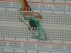
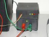
I was thinking about migrating a servo control system I built previously with ATtiny15L into a PIC12F675,found it impossible to access the PIC however(chip ID read 0x00),I noticed the 12F675 is somehow a little different according to some limited info I have in hand but not sure how exactly.Here's my hardware configuration:
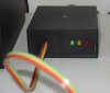
It's a minimized circuit:Vdd = +5V,GND = ground,Vpp,CLK,DAT all connected to corresponding pins on the ICD2's cable.The chip has never been touched since shipment not long ago.
Do I have to do something to the hardware to help the ICD2 access ICSP mode?I searched this forum and found this:
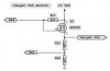
Is there a same problem with ICD2?What if I add a transistor to Vdd that switches on it right after Vpp is applied?My gratitude in advance!
I was thinking about migrating a servo control system I built previously with ATtiny15L into a PIC12F675,found it impossible to access the PIC however(chip ID read 0x00),I noticed the 12F675 is somehow a little different according to some limited info I have in hand but not sure how exactly.Here's my hardware configuration:
It's a minimized circuit:Vdd = +5V,GND = ground,Vpp,CLK,DAT all connected to corresponding pins on the ICD2's cable.The chip has never been touched since shipment not long ago.
Do I have to do something to the hardware to help the ICD2 access ICSP mode?I searched this forum and found this:
Exo said:Don't know about picall, but some programmers, like jdm, have problems with the 12f675 when running on internal oscillator. They turn VDD on before VPP and the pic starts running its program wich prevents it from going into programming mode, maybe the picall's problem is similar...
Is there a same problem with ICD2?What if I add a transistor to Vdd that switches on it right after Vpp is applied?My gratitude in advance!