Continue to Site

Welcome to our site!

Electro Tech is an online community (with over 170,000 members) who enjoy talking about and building electronic circuits, projects and gadgets. To participate you need to register. Registration is free. Click here to register now.

  • Welcome to our site! Electro Tech is an online community (with over 170,000 members) who enjoy talking about and building electronic circuits, projects and gadgets. To participate you need to register. Registration is free. Click here to register now.

CANBus / MCP2515 question

Status
Not open for further replies.

Sam Jelfs

New Member
Hi all, and thanks for the replies to my other thread so far... I'll leave you all alone soon I promise ;)

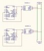
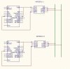
quick question, I'm hoping to use MCP2515's to connect between two devices, but what i want to know is ow to connect them up, can I connect TX on device A to RX on device B and vice versa, or do I need to go through a transceiver such as MCP2551?

Cheers

Sam J
 
Ah, yeah, it's the old problem of what perspective the label is written from:

"It's labelled 'input'. Is this the input for this system, or is it saying this is the 'output' for the input signal to the other system!"

Typically, it's labelled so like-labels get connected together (like how the + and - sign on a battery get connected to the + and - sign on the connector.)

So...

CAN controller (possibly integrated into uC)<->CAN driver:
==========================
RX<->RX
TX<->TX

CAN-Driver<->Other CAN-Drivers:
==========================
CANH<->CANH
CANL<->CANL

It sounds like you want to connect one CAN controller directly to another CAN controller. Although this probably will work, it defeats the purpose of CAN. A CAN line driver is needed to produce the differential signalling, filtering, and protection. The controller connects to the driver on the same PCB, and the driver connects to the primary line that runs long distances to other devices that each have their own CAN-drivers (also connected to their own can controllers).

All the controller does is translate data. The driver is what actually sends the data.

EDIT: Oops. Didn't give you enough credit. Missed your last sentence. Yes. You need to go through a transceiver for the reasons stated above. YOu also used a better word- transceiver. I was trying to think of a word to portray a driver(transmitter) and receiver in one.
 
Last edited:
So something like the circuit below should work? what sets the voltage on the transmission lines? do they require a power source other than the transceivers?

Transceiver Datasheet

Thanks for the help :)

Sam J

edit - Forgot to attach the circuit, doh...
 

Attachments

  • canbus.JPG
    canbus.JPG
    49.3 KB · Views: 700
You can have 3.3V transmission lines or 5V transmission lines. There may be others as well. Some transceivers use the same supply for both sides, some have separate power pins. In this case, you can use different logic and line voltages. You can use the same supply in this case, or an isolated supply (to protect against transients in the transmission line). .

Your schematic has the right idea, except you need 120ohm termination resistors at both ends of the line to prevent reflections (all other connections to the line must go in between these two resistors. Go to microchip or atmel website and search their app note on the CAN protocal. Some ICs also have a third pin so you can set the neutral voltage of the line (with two 60 ohm terminations resistors per end with this neutral pin connecting at the mid point)
 
Last edited:
So this should work (see below, res/1 and res/2 = 120:eek:hm: )

I was getting confused by the app. notes giving the output voltage levels of the chip on to the canbus, but then saying that it supports both 12v and 24v systems... which is neither its output / input characteristics or its Vdd...

anyways, thanks for helping out a n00b.

Sam J
 

Attachments

  • canbus.JPG
    canbus.JPG
    42.9 KB · Views: 423
Sam Jelfs said:
So this should work (see below, res/1 and res/2 = 120:eek:hm: )

I was getting confused by the app. notes giving the output voltage levels of the chip on to the canbus, but then saying that it supports both 12v and 24v systems... which is neither its output / input characteristics or its Vdd...

anyways, thanks for helping out a n00b.

Sam J

Yeah, I'm not sure what they mean by that either. I'm pretty sure they aren't talking about common mode voltage. I don't think the datasheet says the supply voltages for the line side can get that high either.
 
Status
Not open for further replies.

Latest threads

New Articles From Microcontroller Tips

Back
Top