Continue to Site

Welcome to our site!

Electro Tech is an online community (with over 170,000 members) who enjoy talking about and building electronic circuits, projects and gadgets. To participate you need to register. Registration is free. Click here to register now.

  • Welcome to our site! Electro Tech is an online community (with over 170,000 members) who enjoy talking about and building electronic circuits, projects and gadgets. To participate you need to register. Registration is free. Click here to register now.

Can these two circuits be tied together

Status
Not open for further replies.

H2OWiz

New Member
Change of circuit helped but MOSFET still has problems

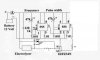
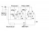
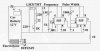
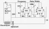
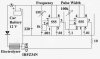
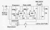
I need to control the current output of a MOSFET. I belive this can be done by controling the voltage to the gate of the MOSFET. I found the MIC29152 will output 1.24 to 13.6 volts which is what I need for the MOSFET control. But I also need to control the frequency and pulse width of the MOSFET. I want to use the 555 chips for the frequency and pulse width and hope to somehow tie this the the voltage from the MIC29152. Does anyone know if I can use a transistor for this or maybe another MOSFET. This is the transistor on the schematic marked ?
 

Attachments

  • controler.jpg
    controler.jpg
    61.1 KB · Views: 311
Last edited:
The control on the MOSFET would be open-loop but otherwise you're getting close. You do realize that this will cause a lot of dissipation in the MOSFET when it's only partially on.

You need to load the emitter of the BJT to ground (maybe 1K?) and put a resistor in the base of the BJT (maybe 33k?).

hint: Some people (including me) find it very hard to follow, when a new thread is opened instead of taking the problem to its conclusion.
 
The problem of the Mosfet blowing up before might be because your circuit has nothing to turn off the Mosfet. It needs a resistor from the gate to ground to turn it off.

Boy oh boy will the Mosfet get hot if you don't turn it on fully. It will melt inside before its outside gets warm.

Why does your water conduct 30A or more? Acidic?
 
This may not mean anything, but the pots connected between pin 7 and Vcc should have a fixed resistor so that the maximum current is limited.
I have been able to control the current of a mosfet with some feedback. I put a resistor between the source and ground. The voltage across the resistor is a sample of the source current. It may not work on this circuit tho.
 
Why not turn it into a proper buck converter? A better solution would be a dedicated PWM chip but you could do it with 555's:
 

Attachments

  • controler.jpg
    controler.jpg
    99.7 KB · Views: 364
Back to origional circuit

I went back to my origional circuit but added a 10 ohm resistor as shown in the Kchriste post. Thanks. This did eliminate the heat problem I was having and I was able to control the pulse width for some time where as before the circuit would only last a minute. I was able to control the current through the amp meter and varied it from about 15 to 25 amps. No heat detected although I do use a rather large heat sink. After several tests of different frequencys and pulse widths the pulse width was no longer controllable. However the circuit contiuned to run although the amp meter was pegged. Still a lack of heat. I checked the 555 without the MOSFET and the pulse width was still functioning so it looks as though the MOSFET has failed. Any one have any ideas about how to fix this.
 

Attachments

  • CONTROL.jpg
    CONTROL.jpg
    299.5 KB · Views: 226
You could use several MOSFETs in parallel or upgrade to a MOSFET with a higher current rating. The IRFZ34 is only rated at 30A and you are running it at 25A. You need more of a safety margin. Try 3 new IRFZ34 MOSFETs in parallel on the same heatsink. Use short lengths of thick (#14 AWG) buss wire to parallel the drain and source terminals of the MOSFETs. The best solution is to use a 100A MOSFET. Something like the IRFP064v in a TO-247 case etc.
 
Last edited:
Added LM317 to reduce voltage to gate.

I just added the LM317 voltage regulator to keep the voltage on the gate of the MOSFET at 3 to 6 volts so I can control the amps to the electrolyzer. I am trying to get 15 to 20 amps out put. Now when I hit about 10 amps the MOSFET gate stops responding and the drain to source is full on which quickly kills the MOSFET. I had better run times before I added the LM317, about 1 minute, but still had the same problems with the MOSFET. One additional problem that I have now since adding the LM317 is the 555 that controls the pulse width is also burning out. How can such a simple circuit be so difficult. If any one knows what I am doing wrong please let me know, and thanks.
 

Attachments

  • control scan.JPG
    control scan.JPG
    53.3 KB · Views: 261
The minimum allowed supply voltage for a 555 is 4.5V.
The output high voltage of a 555 is about 1.5V less than its power supply voltage.

The Mosfet needs 10V on its gate to be turned on fully. If the Mosfet is not turned on fully then its chip will melt.

Usually the duty-cycle of the pulse width controls the average current of a Mosfet circuit.
 
OK. Sounds like what I need to do is adjust the LM317 to a higher voltage setting and then adjust the pulse width to drop the amps to a working range of 15 to 20. I don't think I can set the LM317 to 11.5 volts as this is only .5 volts difference for the power supply voltage and I think the LM317 will only allow a 2 volt difference. I will set it to at least 10 volts or as high as possible and try again.
 
Last edited:
The LM317 is not wanted in your circuit. Its max output voltage is about only 10.5V with a 12V supply then the max output of the 555 is only 9V which is too low.
 
Removed LM317 but now the filter cap keeps blowing up.

I built a new board with out the LM317. You will notice on the schematic there are 2 lines to the #8 pins of the 555s. I plan on installing .1 caps here for filters but have none available at this time. I set the pulse width to 800 ohms which on an ohm meter read 5.32 volts which gave 12 amps out through the electrolyzer. However in a few seconds I noticed the current going down slightly the a few seconds latter going up and the the filter cap blew out. I have tried this twice. Is my filter cap to small ? I am including a snapshot of the gate voltage pulse at line 3 on the pulse width 555 taken after the 10 ohm resistor. I am not able to take this reading with the MOSFET charged at this time as my computer is in the house and the car with the power source is outside. Can someone help me understand how to read the frequency of the snap shot. I understand the time base but not how to read the screen. Is each square 50 µs ? Please help.
 

Attachments

  • control scan.JPG
    control scan.JPG
    45.7 KB · Views: 207
  • gate.JPG
    gate.JPG
    60.2 KB · Views: 190
I think each graticle is 50us.
Then the frequency looks like about 5.7kHz. The waveform has rounded edges due to the length of the cable to your pc (its high capacitance) and that a pc 'scope doesn't show harmonics above 20kHz.

The duty-cycle is about 40% so if your meter reads 10A then the current in the Mosfet is 12.5A.

The filter capacitor will have a high ripple current if the battery is far away, the connecting wires to the battery are thin or if battery is not fully charged. A capacitor with a high ripple current rating is physically large.
 
The cell I designed is capable of producing enough gas to run a 4 cylinder engine however no I only want to introduce a small amount of hydrogen to start. Full hydrogen requires an independent water injector.
 
Status
Not open for further replies.

Latest threads

Back
Top