Continue to Site

Welcome to our site!

Electro Tech is an online community (with over 170,000 members) who enjoy talking about and building electronic circuits, projects and gadgets. To participate you need to register. Registration is free. Click here to register now.

  • Welcome to our site! Electro Tech is an online community (with over 170,000 members) who enjoy talking about and building electronic circuits, projects and gadgets. To participate you need to register. Registration is free. Click here to register now.

Can someone please take a look at my circuit?

Status
Not open for further replies.

mindctrl

New Member
Hi everybody,

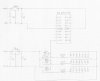
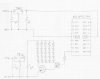
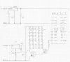
I drew up what I think my circuit should look like today. I'm basically trying to flash LEDs using a transistor, and then power the transistors using a PIC. I'm going to be powering the whole thing off of 12V car power supply (lighter socket). I don't have any fancy circuit drawing programs to do this on, so I had to do it the old fashioned way, by hand on some graphing paper. :) Thanks in advance!

[/img]
 

Attachments

  • led_circuit.jpg
    led_circuit.jpg
    29.8 KB · Views: 690
Argh! Terribly sorry about the double post - can an admin please remove that first one? Thanks and sorry for the mixup.

--mindctrl
 
Transistors are the wrong way around c-e. Emitter to GND and led's + resistor in collector line.
Not a good idea to tie all the bases together. Each base should have its own resistor going to the PIC.

PIC needs a resistor on the reset pin to +ve
 
It's also very bad practice to put LED's in series!.

Try looking at my IR tutorial hardware, this shows how to drive LED's from a PIC - notice I use an NPN transistor, with the LED's in the positive rail.
 
Nigel made a typo, for better efficiency put more LED in seriel. Probably no need a stabilized voltage for LED section. For 7812 not enough 12V input for proper work.
 

Attachments

  • led_circuit2.jpg
    led_circuit2.jpg
    35 KB · Views: 647
Sebi said:
Nigel made a typo,

Yes I did :oops:

Should have read "it's very bad practice to put LED's in PARALLEL".

Series is how they should be done, depending on the supply voltage available. If you parallel LED's you should use a seperate current limiting resistor for each series chain of LED's.
 
Just a quick comment about the capacitor symbols.

When using the American symbol which has the curved line for one of the plates, the curved plate is the -ve, the straight plate is the +ve.

JimB
 
Great!!

Thanks for the updated circuit diagram!

Should I go with that, or just get rid of the 7812? If so, should I power the LEDs off the 7805? Is that do-able? I imagine it would be, if I wired them in parallel... Thanks again guys. :)
 
why not run the series configuration like sebi's drawing?

But if you do run them all in parrallel, definitly run them off 5V. that way you should be able to use 1/8W resistors.
 
I don't think I can run them in series, because of the fact that my voltage will not be able to supply them all at only 5v. What about if I ran them at 5v, on a parallel setup?

I was told that would run too hot. Man, this is starting to get hard. Does anybody have a concrete recommendation that I could just do? Let's say I want to run everything off of parallel circuit, what would I need to do to make this work?

Thanks for all your help
 
Maybe I should restate my question :)

I have 30 LEDs, running at 1.5 volts, with 100ma apiece. I have a 12v feed coming into a 7805 regulator, reducing it down to a 5v feed. How do I power the LEDs with transistors? Do I wire them in series or parallel?
 
Is there any reason to use a PIC and not a simple 555? :?

Or do you need to flash a sequence or something?
 
30 LED parallel (100mA/LED) 3A! The 7805 can supply only 1A. The direct parallel connection not recommended, cannot find 5...15 LEDs with exactly same properties.
When You connect 6 LEDs seriel, need minimum 10V supply voltage, but only 100mA for 6 LEDs!
Build 5 of this group, need 0.5A for 30 LEDs, so the power lost 1/6.
 

Attachments

  • led_circuit2_130.jpg
    led_circuit2_130.jpg
    36.3 KB · Views: 499
I always use 0.1uF ceramic disc caps on both the input and output of the voltage regulators.

And maybe a single 10uF elec on the output too.

Add a 0.1uF ceramic disc cap as close as possible to the pic too. -- Just good practice.
 
I don't get it. Why do you need 317 or 7812 for the LEDs? As I understood it, whole circuit is powered by car acc...
 
As you may or may not know, automobile voltage is extremely irregular. It can spike anywhere from 13v to 16v in a matter of seconds. By using a 7812, I can step down the voltage to a constant 12v coming through, while it's not perfect, it should work for the circuit I'm building. Think of it as a really lazy man's line conditioner.
 
Status
Not open for further replies.

Latest threads

New Articles From Microcontroller Tips

Back
Top