Continue to Site

Welcome to our site!

Electro Tech is an online community (with over 170,000 members) who enjoy talking about and building electronic circuits, projects and gadgets. To participate you need to register. Registration is free. Click here to register now.

  • Welcome to our site! Electro Tech is an online community (with over 170,000 members) who enjoy talking about and building electronic circuits, projects and gadgets. To participate you need to register. Registration is free. Click here to register now.

Can someone just check my calculations for this project please?

Status
Not open for further replies.

bigal_scorpio

Active Member
Hi to all,

I have decided to build a step up circuit using a TL97acn IC.

I have 12v input and am aiming for 36v out at 60mA.

This is well within the specs of the IC and the circuit is quite simple but the calculations to get the values are making me think I must be working something out wrong.

If someone could check this for me I would be grateful and then could stop worrying that I will release the ICs magic hidden smoke hehe.

I have posted my working out and the datasheet it comes from.

Thanks in advance..Al
 

Attachments

  • TL497ACN.pdf
    453.2 KB · Views: 147
  • calc1a.JPG
    calc1a.JPG
    74.3 KB · Views: 173
You inductance calculation is wrong.

To get 360 mA from 12 V in 100 µS you want a 3.3 mH inductor, or 3300 µH. That is higher than 50 - 500 µH, by 6 times, but that is closer than 3.3 µH is to 50 µH. I think that 100 µs is quite a long time and the switching frequency is too low.
 
You inductance calculation is wrong.

To get 360 mA from 12 V in 100 µS you want a 3.3 mH inductor, or 3300 µH. That is higher than 50 - 500 µH, by 6 times, but that is closer than 3.3 µH is to 50 µH. I think that 100 µs is quite a long time and the switching frequency is too low.

Hi mate,

I chose the 100uS as it was an easy figure and roughly mid way between the shown limits.

Would it be better to change the on time to a smaller one? Also any suggestions on the output cap as however much I read the sheet I can't find any info on choosing it, ripple is not mentioned at all!

Any help is appreciated, thanks Al

Edit. I can't get the Ton above 15 using the formula given without going above the suggested 50 to 500uH values, worked out as follows:- L (uH) = Vi divided by I(pk) x Ton which in my case is 12 / .360 = 33.333r and saying Ton is 15 gives a final value of 500.

Considering they say choose inductance between 50 and 500 uH and Ton between 25 to 150uS, how can this formula ever work out in their expected range? Unless I am making some weird mistake?
 
Last edited:
100 µs as the Ton will mean about 30 µs Toff, and the total is 130 µs, so the frequency is about 7.6 kHz, which might be audible, if there is any movement on the inductor.

The IC data sheet gives the formula for the output capacitor, but you have to decide how much ripple your circuit can stand. You know that you want 36 V and 60 mA so you must know what sort of load it is. If you tell us, we might be able to advise how much ripple will be tolerated.

The only problem with the formula on the data sheet is that it ignores the ESR of the capacitor. That will add Ipk * ESR to the ripple.

Hi again mate,

I don't see any worries of audible inductor being a problem, as the circuit will be in an isulated area. As to what the circuit is for, it is meant to drive 3 strings of white LEDs (9 per string) at a max of 20mA per string, so the only consideration for ripple would be if the LEDs visibly flicker. If the circuit does not care what the value of the ripple cap is I was planning on just using a decent size electrolytic say 100uF to prevent flicker, but would this value impact on the ICs operation at all? BTW see previous post which crossed as we both replied.

Thanks Al
 
You need something to keep the current in each string equal. A resistor of 50 - 100 ohms in series with each string would make sure that the current are similar.

You could have a huge amount of ripple at those sorts of frequencies without it being visible. Some people say that 100 Hz isn't visible, but I find it incredibly distracting, but 7 kHz is probably impossible to see. Also, any capacitor will mean that the LEDs don't turn off when the inductor current drops to zero. Even at 100 Hz, as long as the minimum LED current is more than about 5% of the average current, the flicker is much less visible.

If you are running LEDs, you might want to arrange the feedback on the IC to control the current rather than the voltage.
 
If you are running LEDs, you might want to arrange the feedback on the IC to control the current rather than the voltage.

Hi again, Yes I thought of that myself earlier but discounted it as there are 3 strings in parallel and if any string lost continuity or simply drew less then the others would be given the extra current, so 2 strings could fry fairly quick just because of an open circuit on the other or am I wrong? As to the delayed off with a large cap, it won't make any difference as when the circuit is not powered the LEDs will be hidden (box closed).

Again, any ideas on better values for the inductor and timing? The vagueness of the datasheet is really worrying me and I have no experience of this type of circuit so I really need reassurance on this.

Al

Thats why I went for voltage an they will indeed have 1 resistor per string
 
Careful. The data sheet specs Vo 2X Vin and 30 volts max.
 
As to the delayed off with a large cap, it won't make any difference as when the circuit is not powered the LEDs will be hidden (box closed).

The capacitor is there to reduce flicker. It doesn't need to be large with those frequencies. 100 µF will reduce the voltage ripple to about 0.1 V.

Once the power turns off, the LEDs may be still glowing dimly a second or so later, but it will be very much dimmer very soon.

Again, any ideas on better values for the inductor and timing? The vagueness of the datasheet is really worrying me and I have no experience of this type of circuit so I really need reassurance on this.

There is a wide choice of inductor or timing because those change with supply voltage, output voltage and current. Also there is a compromise between size and efficiency. A larger inductor, and slower switching frequency, will increase the efficiency.

Your application uses a larger inductance than the normal range because the current is far lower than the 500 mA maximum. It is not really a problem, because a 3.3 mH inductor capable of 60 mA isn't very big.

As for current control, LEDs can fail, but they are very reliable if not overdriven. As for LEDs taking less current, it is important that the circuit controls the current in LEDs. That is why you should have resistors in series with each string. Once you have done that, you won't get some LEDs taking a different current.
 
Hi again folks,

I am getting really flustered now with the equations and results of them.

I have dropped my voltage requirement from 36v to 28v so as to be well within the ICs limits but:-

Here are the new values Vin =12v, Vout = 28v, Iout = 60mA, I(pk) = 280mA.

If I use the recommended value for the inductor of between 50 to 500uH then the Ton value does NOT match what they say.

If I use a timing cap of say 220pF then according to their scale I would expect the Ton to be between 20 and 21uS but my calc gives 18.3333.

Please please can someone look at the equations and see what I am doing wrong.

Al
 
If I use the recommended value for the inductor of between 50 to 500uH then the Ton value does NOT match what they say.

It won't match with such a small current. Just use a larger inductor to keep the current down and the Ton up to what they suggest. It won't hurt.

If I use a timing cap of say 220pF then according to their scale I would expect the Ton to be between 20 and 21uS but my calc gives 18.3333.

Sounds close enough to me. That is a very small difference.
 
Hi again guys,

So I finally built it and sad to say it doesn't work.

All I get out is roughly the same as volts in.

These are the values I used. R1 = 26k8 R2 = 1k2 Rcl = 1.78ohm L = 5.5uH and Ct = 320pF (nearest I could get to the 300pF that my calculations gave)

Can anyone sim this circuit please or confirm it somehow?

Thanks Al
 
Last edited:
Hello there,

Are you saying you are using an inductor of only 5.5uH ? That's got to be way too small for what i think your frequency is. Back in the 70's i dont think they had any chip that would work with an inductance that low. I'll have to take a better look at the data sheet tomorrow if you dont get it working by then. Basically it looks like a boost converter with built in drive transistor and diode, but it doesnt look like it goes too high in frequency which brings us to a question. Did anyone ask you yet, why exactly do you want to use such an old design chip like this anyway?
 
Last edited:
Hi mate,

I chose the 100uS as it was an easy figure and roughly mid way between the shown limits.

Would it be better to change the on time to a smaller one? Also any suggestions on the output cap as however much I read the sheet I can't find any info on choosing it, ripple is not mentioned at all!

Any help is appreciated, thanks Al

Edit. I can't get the Ton above 15 using the formula given without going above the suggested 50 to 500uH values, worked out as follows:- L (uH) = Vi divided by I(pk) x Ton which in my case is 12 / .360 = 33.333r and saying Ton is 15 gives a final value of 500.

Considering they say choose inductance between 50 and 500 uH and Ton between 25 to 150uS, how can this formula ever work out in their expected range? Unless I am making some weird mistake?

Hello again,


The simple answer is that whomever wrote up that data sheet made a mistake or else they meant to imply some sort of other conditions to those values. In any case, you should ignore that very part of the data sheet and proceed according to the equations given and whatever inductance you end up with you end up with, and that's what you use, whether it is 50uH or 5000uH.

The equations, unlike the rather restricted range they quoted, look correct so we'll use them. They should render us some good enough values to use in an actual circuit.
We'll start with a Ton of 100us and then work our way down by dividing that in half twice, giving us 50us and 25us, and then you can pick your favorite set of values :)


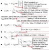
For an output of 28v we set the target output voltage to 29v to make up for some losses.
With Vout=29 and ILoad=60ma we get an iPeak of:
iPeak=2*ILoad*Vout/Vin
with the constraint that iPeak<450ma for some margin of error, and we get:
iPeak=2*ILoad*Vout/Vin=0.290 amps
(and that meets the iPeak constraint so we're ok so far)
and with a Ton=100us that means L comes out to:
L=Vin/iPeak*Ton=0.004138 Henries
and we'll increase that by 10 percent for some margin of error so we get:
L=0.004*1.10=0.0044 Henries.
We can also calculate Toff:
Toff=Ton*Vin/(Vout-Vin)=70.6us
and the duty cycle D:
D=Ton/(Ton+Toff)=0.5862
and just to check the output voltage:
VoutCheck=Vin*1/(1-D)=29.0 volts
and the average input current is:
IinAvg=ILoad/(1-D)=0.145 amps
With a max output ripple of:
Vripple=0.5 volts
we can approximate the value of the output capacitor:
C=(Ton*Vin/Vout)*(iPeak-ILoad)^2/(Vripple^2*iPeak)=30uf

To recap:
Ton=100us
L=4.4mH, and
C=30uf.

All of the above were based on an on time Ton=100us, but if we cut that in half then we can also
cut all of the component values in half too. This would lead to the following:
Ton=50us
L=2.2mH
C=15uf

Since now that is based on a Ton=50us, if we cut that also in half we can then halve all the other
values again. This leads to:
Ton=25us
L=1.1mH
C=7.5uf


So there you have it, three different sets of components to choose from.

In all of these the value of the current sense resistor should be 1 ohm, 0.5 watts.

Another thing to watch out for is the ESR of the inductor. You dont want too high of a series resistance or the output voltage will never be able to reach the required value.

If you are really seeing an output voltage that is just slightly less than the input voltage and all the components are chosen correctly, then there is a good chance that either the chip isnt enabled or the internal power transistor is blown open. This transistor could blow out if the wrong component values were used without that 1 ohm current sense resistor (a short instead of that resistor).
 
Last edited:
Excellent post MrAl.

I would also add that if switch mode converters need a minimum inductor current to work. When the switch turns off, the current in the inductor carries on flowing and turn on the diode. However, the voltage on the diode cannot change instantly. There is capacitance in the inductor, the diode, the switch, the tracks which all has to be charged up before the diode conducts. There is also the matter of how fast the switch is capable of turning off.

All of this means that if you only have a very small peak current in the inductor, the voltage pulse on the inductor will not be large enough. It is difficult to say how much current is needed, but I am fairly sure that was the problem with the 5.5 µH inductor. The stray capacitances etc are not always in the data sheets, so it is a case of trying it out.

With a much larger inductor, say 2.2 mH, there is far more energy stored at the same peak current, so there is plenty of energy to ride over the turn off time of the switch, charge up all the stray capacitances, and still have useful energy to produce the output voltage wanted.

As an aside, in buck converters, at currents far below the maximum current, the freewheel diode never turns on, for the reasons I've just said. They become PWM regulators, and the output current is less than the input current. It is only at 1% or more of the maximum output current that the regulator actually works as intended.

It is for reasons like that that TVs often have a standby power supply, rated at maybe 1 or 2 W, that powers the IR receiver and a relay that applies mains to the real power supply. That gets the standby power right down.
 
Hi Guys,

Thanks for all the help. At last its working! :)

Couldn't have done it without your help guys, thanks again Al
 
Excellent post MrAl.

I would also add that if switch mode converters need a minimum inductor current to work. When the switch turns off, the current in the inductor carries on flowing and turn on the diode. However, the voltage on the diode cannot change instantly. There is capacitance in the inductor, the diode, the switch, the tracks which all has to be charged up before the diode conducts. There is also the matter of how fast the switch is capable of turning off.

All of this means that if you only have a very small peak current in the inductor, the voltage pulse on the inductor will not be large enough. It is difficult to say how much current is needed, but I am fairly sure that was the problem with the 5.5 µH inductor. The stray capacitances etc are not always in the data sheets, so it is a case of trying it out.

With a much larger inductor, say 2.2 mH, there is far more energy stored at the same peak current, so there is plenty of energy to ride over the turn off time of the switch, charge up all the stray capacitances, and still have useful energy to produce the output voltage wanted.

As an aside, in buck converters, at currents far below the maximum current, the freewheel diode never turns on, for the reasons I've just said. They become PWM regulators, and the output current is less than the input current. It is only at 1% or more of the maximum output current that the regulator actually works as intended.

It is for reasons like that that TVs often have a standby power supply, rated at maybe 1 or 2 W, that powers the IR receiver and a relay that applies mains to the real power supply. That gets the standby power right down.

Well thank you Diver.
It was good of you to bring up the turn on/off times of the components, but i think there is a much simpler explanation about the 5.5uH inductor. The minimum Ton time of the chip is spec'd at 19us, and with that much time and a 12v input voltage at the end of the Ton period the current in the inductor would have reached something like 40 amps, and we know that the transistor will never be able to handle that kind of current as it is limited to 1/2 amp. As a matter of fact, due to the input voltage and min Ton time the minimum inductance for this app would be about 456uH. Any lower than that and the current demand exceeds the internal transistors rating. Make sense to you?

I would like to see the finished circuit too.
 
Last edited:
Status
Not open for further replies.

Latest threads

Back
Top