Continue to Site

Welcome to our site!

Electro Tech is an online community (with over 170,000 members) who enjoy talking about and building electronic circuits, projects and gadgets. To participate you need to register. Registration is free. Click here to register now.

  • Welcome to our site! Electro Tech is an online community (with over 170,000 members) who enjoy talking about and building electronic circuits, projects and gadgets. To participate you need to register. Registration is free. Click here to register now.

Can someone explain how this circuit demodulates ?

Status
Not open for further replies.

aidob

New Member
Hi ,

I hav been given this circuit as part of a report in college , it is a receiver circuit ,

the transmitter being an audio signal , pulse position modulated by a 555 times and transmitted by an LED .

the receiver is this

**broken link removed**

it is broken down into 2 main things ,

an active High pass filter

**broken link removed**

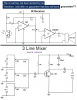
and an audio amplifier with a basic low pass filter

**broken link removed**


can anyone explain , or even point me towards sites or ebooks that will help me understand how this circuit demodulates the Pulse position modulated signal ?
 
I don't think it does. I see no way to recover the original digital message based on the difference in time of the rising and faling edges or the difference between two rising edges, or two falling edges. There is also no clock recovery circuit, just an edge detector and an audio amplifier. Whooo...Hooo!
 
Pulse position modulation doesn't require a special demodulator, all that's required is a low pass filter.

Your circuit doesn't have a low pass filter though. The LM386 is an IC audio amplifier. I think the circuit relies on the fact that the frequency of the pulse position modulation is ultrasonic so you can't hear it.

The input should have a comparator to detect the pulses and eliminate AM signals such as backgorund noise from ambient lighting conditions.
 
my lecturer said that C4 and R5 create the low pass filter (a basic one at that)

or is he wrong ?
 
I agree that I don't think a demodulation stage is necessary other than low pass filtering, which ultimately your ear provides. This is similar in nature to how you can generate an audio signal using a PWM output of a microcontroller. In that case, the width of the pulses vary so the total average voltage varies at the audio rate and when you lowpass filter, you get the audio. In your case the total average voltage varies at the audio rate also, but by moving the position of the pulses around instead of varying their width.
 
aidob said:
my lecturer said that C4 and R5 create the low pass filter (a basic one at that)

or is he wrong ?

Yes, he is wrong.

That configuration is usually referred to as a Zobel network.
It provides a load at high frequencies to ensure stability in the amplifier.

By applying some rather perverted logic it could be considered an LPF because it only loads high frequencies, but that is stretching the imagination.

JimB
 
I already answered about this lousy circuit on another site's forum. This circuit is made to pickup the hum from AC powered lights.

The very poor high frequency response of the old 741 opamp is the lowpass filter, but not a good filter because the opamp's gain is very low because it is inverting and has a very high source impedance.

The LM386 isn't a lowpass filter, it has a good response to higher than 100kHz, even with the capacitor boosting its gain. The zobel network does not affect its frequency response. Look at its datasheet.

It is stupid to have a low input impedance inverting opamp creating a very heavy load on the high output impedance photo-transistor resulting in both not having any gain. I would use a high input impedance non-inverting opamp stage so that the photo-transistor has a lot of gain and the opamp can have any amount of gain you want. Also then a capacitor can be added at the collector of the photo-transistor or across the feedback resistor of the opamp, or both, as a good lowpass filter.
 
Sorry to double post but I just found the other site and see that its opamp biasing problem has been fixed here. It didn't have a negative supply.
The opamp also didn't have the 1k input resistor but it doesn't make much difference.
 
aidob said:
my lecturer said that C4 and R5 create the low pass filter (a basic one at that)

or is he wrong ?
Your lecturer said that?

This just shows the poor standard of education you're been given.

Care to name and shame this college/university?
 
Yeah, let us hear about which college studies about such a lousy circuit.

Oh, maybe the college wants the students to list all the stupid things wrong with its design?
 
You might want to ask the instuctor if his degree came in the mail, and how much it cost. That way you could save yourself a great deal of trouble.
 
Papabravo said:
You might want to ask the instuctor if his degree came in the mail, and how much it cost. That way you could save yourself a great deal of trouble.

You might also ask what his degree is in! - it certainly can't be electronics!.
 
Gee, this is a tough crowd. Like sharks in a feeding frenzy, only here its an incompetence frenzy:) By the way, who is Feynman?
 
Richard P. Feynman, Nobel Laureate and professor of Physics at Cal Tech. In 1964 he published a three volume set, "The Feynman Lectures on Physics". We used Volume II as a text in one of my undergraduate physics class.

Top Google hit:
http://www.feynman.com/
 
I found the original IR Receiver project with its opamp incorrectly biased, and another lousy circuit from another site for the school kids to study.

The new circuit is an audio mixer project using an old BC109 transistor. Look at how it is biased!! No negative feedback, the transistor is a thermometer.
The old BC109 has a current gain of from 200 to 800. This circuit causes severe distortion when the transistor's gain is normal to high because the transistor is saturated.

Both sites have worse circuits that also don't work.
 

Attachments

  • Lousy circuits.PNG
    Lousy circuits.PNG
    53.9 KB · Views: 213
cs1dipper said:
Can anyone tell me what a Risk Processor is and what is it's funtion?

This should really be in a new thread, but as we are here, lets go...

I think you really mean RISC

Reduced Instruction Set Computer

As it says, a processor where the number of basic machine code instructions is less than some others. That does not mean that it is any worse than any other processor, the idea is to make it run faster by not having to do as much decoding of machine code instructions, so taking up less clock cycles and running faster.

Its function? what ever you want it to do.

JimB
 
Status
Not open for further replies.

Latest threads

New Articles From Microcontroller Tips

Back
Top