Electro Tech is an online community (with over 170,000 members) who enjoy talking about and building electronic circuits, projects and gadgets. To participate you need to register. Registration is free. Click here to register now.
Welcome to our site! Electro Tech is an online community (with over 170,000 members) who enjoy talking about and building electronic circuits, projects and gadgets. To participate you need to register. Registration is free. Click here to register now.
Use one 100 ohms for each set of four output transistors.
The driver transistors have nothing to limit their current so if their hFE is high then they will get very hot and leak a lot of current.
That circuit was designed by somebody who knows nothing about electronics. The collector of the driver transistor should be connected to the collectors of the output transistors it is driving to make a darlington. Then the driver transistor current will never be too high.
The pre-driver transistors have a 100 ohm resistor feeding the drivers so use a 1k ohms at the base of each driver transistor.
Use 2.7k to ground at the base of each pre-driver transistor.
The SL100 transistors are driven push-pull so they do not need additional resistors.
- Then I need two 100 ohm resistor for two set of output transistor. May the resistor will be high watt like 5watt, isn't it? Or 1/2watt is fine?
- Oh! remember about resistor watt, look at pre-driver, as you said it will not conduct more current then why there is 5watt at collector and 1 watt at emitter? Is it silly too? May I use normal 1/2watt?
Simply look at the circuit to see that the emitters are grounded and the base goes as high as the datasheet says it does. Only to 1.5V!
How much power is in a 100 ohm resistor with only 1.5V or less across it? 0.0225W which is almost nothing! A 1/4W resistor will be fine.
Oh! remember about resistor watt, look at pre-driver, as you said it will not conduct more current then why there is 5watt at collector and 1 watt at emitter? Is it silly too? May I use normal 1/2watt?
Simply calculate the maximum power in each resistor. The 15 ohm resistor connects to 12V which might be 13.8V when the battery is fully charged and the 100 ohm resistor connects to two base-emitters in series making about 1.7V. So the 15 plus 100 resistors have 12.1V across them which makes their current (12.1V/115 ohms=) 105mA. Then the power in the 15 ohms resistor is only 0.166W and the power in the 100 ohms resistor is 1.1W. The resistors are powered for only half the total time so their actual average power is half. A 1/4W resistor is fine for the 15 ohms resistor and a 1W resistor is fine for the emitter resistor.
Yes the schematic is silly here too.
Did you understand how to connect the driver transistors to the output transistors to make a darlington?
The original circuit was silly too.
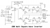
Remove R2, R3, R8 and R9 and replace them with wire.
Replace the huge power 2N3055 transistors Q3 and Q4 with little 2N2222 transistors becaue their current is low.
To have an output as high as 200W, Q7 is FOUR 2N3055 transistors in parallel and the same with Q8.
The Cmos IC needs a resistor, capacitor and zener diode to protect it from voltage spikes on the +12V.
What will you use it to power? Its output is a horrible unregulated squarewave. It does not shut off when the battery gets low so the battery might be destroyed.
- Any transistor will work as Q3, Q4? Even 547, 549 too? May be it's related to its hFE and I(c).
- In maximum, how many parallel transistor can I use? (I think 'driver' is not able to drive ultimate numbers of transistors )
(OK, I will use 12V zener, 0.1uF and 100uF. I am going to use it as a general purpose, to light bulbs, to watch TV etc. Here almost half of the time in a day and night is no electricity due to load scheding (lack). So. Ok i will modify as you say.)
Maybe.
With an output of 200W and if the hFE of the other transistors is low then the max current in Q3 and Q4 is 120mA (useless R8 and R9 are removed).
The max allowed current of a BC54x is only 200mA so at 120mA it works poorly.
Yes.
Lots of circuits on the web are designed by little kids who do not know the details of electronics.
The datasheet of a transistor, simple arithmatic and Ohm's Law tell you if the circuit will work or not.
Little kids do not know how to read or maybe they are blind.
- In maximum, how many parallel transistor can I use? (I think 'driver' is not able to drive ultimate numbers of transistors)
use simple arithmatic and the specs of the transistors.
(OK, I will use 12V zener, 0.1uF and 100uF. I am going to use it as a general purpose, to light bulbs, to watch TV etc. Here almost half of the time in a day and night is no electricity due to load scheding (lack). So. Ok i will modify as you say.)
Yes! Learnt few ideas. BC337 has I(c)= 500mA and works fine at 120mA
And now modified circuit has been ready!!
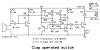
The writer (of the book from where I found the silly inverter circuit) included another Clap operated circuit (His original circuit is dirty so I made new with ExpressPCB). I found this multivibrator little complicated than other. May be it is also his silliness but it is working. Look at two high value resistor 2M2, won't it work if 1Meg?
(oh no! Mistakely I made Q2 upside down! Read it as normal emitter grounded )
The BC547 has a very wide range of current gain from 110 to 800. The CLAP circuit probably will not work with low gain transistors and the flip-flop transistors should be matched.
The BC547C is selected for high gain from 400 to 800 and will work.
Maybe the author built only one circuit and it worked because he was lucky to find BC547 transistors with high gain.
Dear AG,
Is it easy to make same Transformer as an 'output transformer' and same transformer as a 'Charging transformer'?
Any idea, any circuit? Searched few links but can't find! Auto system using Relay
Dear AG,
Is it easy to make same Transformer as an 'output transformer' and same transformer as a 'Charging transformer'?
Any idea, any circuit? Searched few links but can't find!
You need an extra winding on the transformer for charging the battery in an inverter.
A car and bike battery is designed to give a high current for a few seconds to start an engine then immediately be re-charged. It has thin plates that warp and short together if it is used at a fairly high current continuously like when it powers an inverter. Its life is shortened if it is discharged too low and the extremely simple inverter does not detect a low voltage and disconnect it.
An inverter is supposed to be powered from a "deep discharge" battery that is designed with thick plates so it can provide a medium current for a long time in a recreational vehicle (motor home) or fork lift truck and discharging it to a low voltage does not hurt it.
The BC547 has a very wide range of current gain from 110 to 800. The CLAP circuit probably will not work with low gain transistors and the flip-flop transistors should be matched.
The BC547C is selected for high gain from 400 to 800 and will work.
Maybe the author built only one circuit and it worked because he was lucky to find BC547 transistors with high gain.
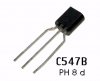
Philips/NXP and Motorola datasheets for the BC547 show a BC547B with current gain of from 200 to 450 when the collector current is 2mA.
A "C547B" might be made by Continental Device India and has the same spec's.
Hi, After almost 17 months 5 days, I remembered the post and was discussed to audioguru lot! ( Actually I discussed LOT and learnt LOT by audioguru anyway )
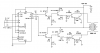
By the modification of audioguru, I had prepared a 4047 based power transistor 200watt This inverter circuit (was uploaded just few post above here). Because of its transistor based design, few more pre-driver or driver transistors are needed here to increase current level for last output parallel transistors.
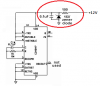
Then today I thought why not to use power MOSFETs instead, to remove all these pre-driver and driver transistors like in attached scematic here (modified by me)? MOSFETs need not to increase current so we can directly drive its Gate and can connect parallel MOSFETs directly, and these are cheaper here than 2N3055 too. Can't we do like this?
If output voltage from 4047 (after 1k resistors) is insufficient to drive four or more other Gates then we can connect a 1k resistor from supply to Gate, cannot we?
( Being long time with AG, mind have become active to modify circuits )
I read somewhere that a power Mosfet has a high gate-source capacitance because it is made from thousands of "Mosfet cells" in parallel so that it has a very low on-resistance.
Your circuit will cause the Mosfets to slowly ramp and get extremely hot instead of switching on and off very quickly producing low heating.
Do it like this:
Nice idea to increase positive square and negative square by NPN and PNP, Wow! And last curiosity is can you assume how many mosfets can I connect in parallel in order to get high power output like 200 watt or 500 watt or 1000 watt etc? (power output per mosfet)
Probably it's better than previous transistor based inverter!
This site uses cookies to help personalise content, tailor your experience and to keep you logged in if you register.
By continuing to use this site, you are consenting to our use of cookies.

")