Electro Tech is an online community (with over 170,000 members) who enjoy talking about and building electronic circuits, projects and gadgets. To participate you need to register. Registration is free. Click here to register now.
Welcome to our site! Electro Tech is an online community (with over 170,000 members) who enjoy talking about and building electronic circuits, projects and gadgets. To participate you need to register. Registration is free. Click here to register now.
I want to use something in this transmitter to understand that the tranmitter is working.. can i use any led or any anything else that would signal that the device is working.
thanks
samina
You could try tuning a radio across the FM band and listen for your signal. Detune it by trimming the capacitor and if the radio responds with noise then you are transmitting.
A LED wired across 100 turns of thin 36SWG wire around a pencil may illuminate if the output power is enough.
There are thousands of very simple FM transmitter circuits similar to this one on the internet that work. This one might not work:
1) The base voltage for the preamp transistor is 0.82V if the battery is new and/or the transistor has high current gain. Then its emitter and collector current are trying to be 1.6mA and the transistor is saturated and does not amplify anything.
2) The base voltage for the preamp transistor is 0.5V if the battery is old and/or the transistor has minimum current gain. Then the transistor is cutoff and does not amplify anything.
My FM transmitter uses a 5V regulator so that the supply voltage for the preamp does not change.
More problems with this one:
3) the oscillator transistor has a very low value 10k base resistor. Then the transistor is almost saturated and does not oscillate.
4) The emitter resistor value is high so the output from the oscillator (if it was biased correctly) is low.
My FM transmitter has a 47k base resistor, a 220 ohm emitter resistor and a 5V regulator for its oscillator.
More problems with this one:
5) The antenna is connected directly to the tuned LC circuit. Then the frequency changes if something moves toward or away from the antanna because then the capacitance of the tuned circuit changes.
My FM transmitter has an RF amplifier that increases the output power and isolates the tuned LC circuit from the antenna.
More problems with this one:
6) It is missing pre-emphasis (treble boost) that all FM radio stations have so the de-emphasis in all FM radios cuts high audio frequencies and makes the sound muffled.
My FM transmitter has pre-emphasis so that everything sounds crisp and clear.
The simplest LED power meter is two diodes connected together and the other ends connected to a LED.
The join of the diodes is probed on the output of the circuit.
Holding one lead of the LED increases the brightness.
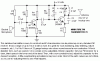
I agree with Colin on this and while likely a little off topic if I wanted to detect in the FM radio band of about 88 to 108 MHz I would use a simple circuit like the one seen here. While the output may not directly drive a LED it could likely drive a 0 to 50Ua meter movement rather than headphones. The 1N34 diode is used as the detector and is a brand new, high tech diode just developed a few days ago. OK, so I lied. Anyway with the receive antenna placed beside the transmit antenna it should work, unless of course I am way off base in which case it won't work. Just tune for the strongest signal, turn off transmitter and on again. If the signal comes and goes, it would be you!
I don't remember if it is Colin or Harry (he also published many FM transmitter circuits) who has an LED field strength circuit.
I used a few parts to rectify the signal so I could peak the output LC on my FM transmitter with my digital voltmeter.
This site uses cookies to help personalise content, tailor your experience and to keep you logged in if you register.
By continuing to use this site, you are consenting to our use of cookies.