bountyhunter
Well-Known Member
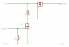
Here's a good P channel FET.
IPP100P03P3L-04
30V, 100A, .004ohm on resistance. Tab is not isolated though. $2.64
Wow, that's a whole lot of FET for the money.
based on experience, I am a little leery of using a 30V FET in an automotive app because of the voltage transients that cruise around the so called "12V" line in a car.

 . I really should just make the design and go from there. Stop worrying so much about looking like a fool and see if
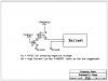
")
