Continue to Site

Welcome to our site!

Electro Tech is an online community (with over 170,000 members) who enjoy talking about and building electronic circuits, projects and gadgets. To participate you need to register. Registration is free. Click here to register now.

  • Welcome to our site! Electro Tech is an online community (with over 170,000 members) who enjoy talking about and building electronic circuits, projects and gadgets. To participate you need to register. Registration is free. Click here to register now.

Can CCP do this on 16F876A? :(

Status
Not open for further replies.

bjox1

New Member
Hello friends,

I am stuck with a problem and will kindly appreciate any help on this.

I have got two TTL signals ranging from 500 Hz to 10kHz. I am trying to measure the delay of one with reference to other. As the signals can be of any frequency I am not sure how to use CCP for this task. I have searched a few topics on here but couldn't find anything appropriate.

I am a newbie and wold really appreciate any help.

Thank you all in advance

bjox
 
Presumably the two frequencies are identical?, otherwise it wouldn't be possible.

If you XOR the signals together, this will give you a pulse representing the phase difference between them.
 
Hi Nigel,

Thank you for the reply.

Nigel Goodwin said:
Presumably the two frequencies are identical?, otherwise it wouldn't be possible.
I am sorry for not providing enough info. YES, the two signals at any given time will have the same frequencies.

If you XOR the signals together, this will give you a pulse representing the phase difference between them.
I am very thankful to you for giving this idea but would really appreciate if you could explain it in a bit more detail. Probably if there's a circuit to look at?? For instance, what will be the output from an XOR and what will be the input to my PIC?? And finally what method I will have to use to get the phase difference in the PIC? [I apologise if I ask too much]


Thanks in advance Nigel.

-I am pretty much new to the electronics :(
 
Last edited:
Have a read of this thread. For some reason the OP has deleted his initial question but he basically wanted to find the phase difference between two signals.

Mike.
 
Hey Pommie,
Thanks for the thread. I had a look at it and it seems a gr8 technique. The only concern is whether I could measure the phase at different freq??

I mean will it work if the signals are at 9.9kHz or in the second case if the signals are at 990Hz?? Please enlighten me!

Thanks.
 
If you use a 20MHz crystal then you will be able to measure 2μS periods. It really depends how accurate you want it.

Mike.
 
Last edited:
bjox1 said:
I am very thankful to you for giving this idea but would really appreciate if you could explain it in a bit more detail. Probably if there's a circuit to look at?? For instance, what will be the output from an XOR and what will be the input to my PIC?? And finally what method I will have to use to get the phase difference in the PIC? [I apologise if I ask too much]

Draw yourself some little diagrams and work it out, it will help you understand it.

All you need to know is that an XOR gate sets the output HIGH, when the two inputs are DIFFERENT, if the two inputs are the same, them the output is LOW.

So get a sheet of graph paper, draw your two input waves on it above each other, then follow the rules above to draw the output waveform below them. Do this for various phase differences, this should make it all clear.
 
Hi Pommie and Nigel,

If you use a 20MHz crystal then you will be able to measure 2μS periods. It really depends how accurate you want it.
I was looking for something with a very high accuracy. I mean I calculated [ and I saw some of ur replies to the same OP] and :
For 1kHz signals- 10us*100 is 1ms i.e. 100 is the max value therefore 3.6 deg for every counter.
& for example for 10kHz signals- 10us*10 will be 100us i.e. 36 deg for every counter.
So I was wondering if I could eliminate this error or probably a technique which is independent of the signal frequency?

Hi Nigel,

I am sorry for asking this again but I am kind of struggling in analysing the XOR technique [probably because Im in my first year :D
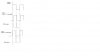
]. If you see the diagram I have attached, if the second signal is say 50 deg lag, and if I feed these two signals to XOR gate, then one signal will be high and the other will be low and the output from XOR will be high all the time. I don't know how can I find the phase difference from there? :confused:

I apologise if I ask a bit too much basics.

Thanks again.
 

Attachments

  • Diagram.jpg
    Diagram.jpg
    15.8 KB · Views: 347
Last edited:
Your diagram clearly shows a time when one is HIGH and one is LOW, when both are HIGH, and when both are LOW, bear in mind to have a phase difference you can measure both waves must be exactly the same frequency.
 
Nigel Goodwin said:
Your diagram clearly shows a time when one is HIGH and one is LOW, when both are HIGH, and when both are LOW, bear in mind to have a phase difference you can measure both waves must be exactly the same frequency.

Mate I am so sorry but I don't understand what to do with the output.:( :( :eek: :eek:

I am so so sorry but please enlighten me. I think my brain hates me!

Thanks Nigel.
 
Like I said, draw a diagram - it's easy - heres an example, top two are the two input waveforms, bottom one the output from an XOR. The bottom waveform is a direct representation of the phase difference.
 

Attachments

  • phase.gif
    phase.gif
    633 bytes · Views: 291
Nigel Goodwin said:
Like I said, draw a diagram - it's easy - heres an example, top two are the two input waveforms, bottom one the output from an XOR. The bottom waveform is a direct representation of the phase difference.

Dear Nigel,
I am so so thankful to you for explaining this to me in such a detail.

As u have suggested me to draw a few cases, I have attached a diagram where I have assumed two cases of delayed signal [named as signal2]. As far as I could imagine [I might be wrong] that if we take a reference point on signal [signal1] on the rising edge of the pulse, the delay signal will possibly have the two cases:
1) if signal2 arrives as low = that means 0-180 deg delay &
2) if signal2 arrives as high = that means the delay signal [signal2]has
crossed the 0-180 deg of delay range and now
it's in 180-360 deg range.

In the attached diagram, I have taken two such cases, one for 10 deg delay and second one is for 350 deg delay and I have found out that the output pulse from XOR gate has the same pulse width.
Now that implies that for any delay value [in deg] between 0-180 [say 'x'] will have the same value for the signal with a delay of 360-x deg[ In my case,10 deg will be same as 360-10 =350 deg]. I am all confused about how to calculate the phase on these cases?? :(

I apologise Nigel if I have over thought it but I would really appreciate any further help on this matter.

Thank you soo soo much .

Ps: I apologise if the diagrams are not upto the scale.
 

Attachments

  • Diagram1.jpg
    Diagram1.jpg
    26.7 KB · Views: 282
Last edited:
You are correct, 10 degrees and 350 degrees will read the same, because they are the same - are you needing to know which leads or lags as well?.

Perhaps you might try telling us exactly what you are trying to do?.
 
Nigel Goodwin said:
You are correct, 10 degrees and 350 degrees will read the same,
Perhaps you might try telling us exactly what you are trying to do?.

Hi Nigel,
Sorry about the late reply.

Well I am at Uni [first year] and this task is a part of our module. There are a few circuits given by technician which introduce delay [0-360 deg].

So we have same signals [same freq at a given time] but one is ref and the other signal goes through these circuits which introduce resp delay. As I mentioned earlier, I have to measure the phase diff but the freq can range from 500Hz to 10kHz.:eek:
because they are the same - are you needing to know which leads or lags as well?.
Well, I have to measure the delay of signal2 with repect to signal1. Hence my reference point is signal1. I hope this might give you a rough idea! I apologise again for being so stupid.

Is it still possible to achieve 0-360 phase measurement using XOR technique??

Thanks once again Nigel.
 
Last edited:
Hi Nigel,
Thanks for the reply.
As the signal always lags, detect the start of the reference pulse, then start counting while you wait for the start of the following pulse.

Will I still need an XOR gate for this?? I mean I can just wait for signal1 to get high, start counting till I get next rising edge on signal2 [exactly what Pommie did in the previous post]. :confused:

Thanks again Nigel.

<EDIT>
Nigel,
I have found this diagram from a website [attached]. The only other way to find the phase diff of 180+ is that if you look at the signal2 or RX signal waveform and XOR output waveform together [in the diagram], for the phase diff between 0-180, when the signal2 [delay signal] rises, the XOR output is low. For example, for the case of 45 deg, as the signal2 rises, the XOR output is low and for 315 deg, as the signal2 rises, the XOR is high.

Am I right in assumin that if I use a bit test for this case, I can fix the problem??
Lastly,if we feed the XOR output to PIC, will I be using counter to find the width of the signal?? If so then wouldn't the counter value be varied? I mean say for 45 deg of phase diff [for 1000Hz signals] the counter will give 'x' value and for the same phase diff [now for 10 kHz signal] the counter will give less than 'x' value?? So if I read the counter value on the output, I will not b getting the same 45 deg value!

I am so so sorry I sound a bit annoying but I need your kind help on this matter.

Thanks again for your time Nigel.
 

Attachments

  • XOR.jpg
    XOR.jpg
    40.9 KB · Views: 294
Last edited:
Nigel Goodwin said:
If you're using different frquencies you need to measure both the HIGH period and the LOW period, the phase difference is the ratio between them.

Sorry Nigel, I am finding very hard to analyse ur solution :(. Please enlighten me.

If you're using different frequencies

I may have explained it wrongly. That’s the whole task:
1) User will choose any frequency from 500 Hz to 10kHz.
2) Then same frequency signal will be tap down to TWO signals. One will be the reference and the other will go through this unknown delay circuit.
3) My aim will be to find the value of the phase difference hence determining the unknown circuit [phase value].

I am sorry for not explaining it clearly.

Awaiting ur reply Nigel.
Thanks again.
 
Do you need to calculate time difference or angular difference? I.E. 2mS or 2°.

Mike.
 
Pommie said:
Do you need to calculate time difference or angular difference? I.E. 2mS or 2°.

Mike.

Hey Mikey,
That's a very nice question. :confused:

Well I am expected to show the value at the output pin of my PIC. may be using LED [8 bits]. I think output as the angular difference will help me in this.

<edit>
Pommie, Can u suggest me any technique for measuring the pulse width using PIC?? [In my case, the output of XOR gate i.e. the ON time of the pulse]

Thanks again.
 
Last edited:
Status
Not open for further replies.

Latest threads

New Articles From Microcontroller Tips

Back
Top