Continue to Site

Welcome to our site!

Electro Tech is an online community (with over 170,000 members) who enjoy talking about and building electronic circuits, projects and gadgets. To participate you need to register. Registration is free. Click here to register now.

  • Welcome to our site! Electro Tech is an online community (with over 170,000 members) who enjoy talking about and building electronic circuits, projects and gadgets. To participate you need to register. Registration is free. Click here to register now.

can anyone tel me is there any problem with this circiut?

Status
Not open for further replies.

kpshamilsagar

New Member
can anyone tel me is there any problem with this circuit and any other comments?anything that can be improved?
 

Attachments

  • untitled.JPG
    untitled.JPG
    115.7 KB · Views: 162
can anyone tel me is there any problem with this circuit and any other comments?anything that can be improved?

hi,
I dont see a Vo pin connection for the LCD contrast control.? Pin 3
Also I would place a 100nF cap close the MCU power pins.


EDIT: whats that device connected in series with pin 10 of the MCU.?
 
Last edited:
k fine thank you...is there anything else?rest everything is fine?should i put a potentiometer there?and how much value it should be?
 
Last edited:
sorry,its not possible i didnt make a schematics.because i need it by this friday..assembled.

hi,
I dont mind checking circuits, but its impossible to verify the accuracy without a schematic as a reference.:rolleyes:

EDIT: whats that device connected in series with pin 10 of the MCU.?
 
Last edited:
Is pin 10 only connected to a cap? Where's VCC

Are the 7 segment displays CC or CA (where do they get power?)

Might need a pullup on RESET (pin9) but I'm a PIC guy so the answer may not apply to AVRs.

You really need schematics else who knows.
 
Last edited:
EDIT: whats that device connected in series with pin 10 of the MCU.?
its just a .1uf capacitor...i have some circuits made the same way.if it is not there also not a problem.
Are the 7 segment displays CC or CA (where do they get power?)

Might need a pullup on RESET (pin9) but I'm a PIC guy so the answer may not apply to AVRs.
its CA and there is no big problem if i dont put a reset button na...
 
Last edited:
its just a .1uf capacitor...i have some circuits made the same way.if it is not there also not a problem.

its CA and there is no big problem if i dont put a reset button na...

If its not a problem HOW does the Atmega get its Vcc +V supply.:confused:

Pin 10 is Vcc.??

There is no point in asking for help if your not prepared to listen.:)
 
If its not a problem HOW does the Atmega get its Vcc +V supply.

Pin 10 is Vcc.??

There is no point in asking for help if your not prepared to listen.
please check properly before complaining man...its connected to vcc only na.
and i am a newbee...so please dont blame me if i do some mistake also..please
and i used to use a 100nf capacitor to connect between power wire and mc VCC wire.
till now i didnt get any problem with that.
 
Last edited:
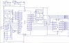
Well it's not going to work without VCC. You're supposed to put a 0.1uF across VCC & GND. Your CA displays also do not have a power source, the CA displays Anodes should be connected to VCC. Your LCD display has no contrast pot, you will need it.

Why two microcontrontollers?

Without a schematic for us to see we're working in the dark.
 
Last edited:
please check properly before complaining man...its connected to vcc only na.
and i am a newbee...so please dont blame me if i do some mistake also..please
and i used to use a 100nf capacitor to connect between power wire and mc VCC wire.
till now i didnt get any problem with that.

Im not complaining about you making a mistake, I know we all make mistakes, but you keep saying there was nothing wrong with pin10.

The atmega will not get any supply thru the 100nF from the power wire, it needs a direct connection.
The 100nF should be across the power wire and the 0V wire.!

Do you see what I am saying.?

EDIT:
Look at this modified image.
 

Attachments

  • untitled.JPG
    untitled.JPG
    20.8 KB · Views: 118
Last edited:
Status
Not open for further replies.

Latest threads

New Articles From Microcontroller Tips

Back
Top