Continue to Site

Welcome to our site!

Electro Tech is an online community (with over 170,000 members) who enjoy talking about and building electronic circuits, projects and gadgets. To participate you need to register. Registration is free. Click here to register now.

  • Welcome to our site! Electro Tech is an online community (with over 170,000 members) who enjoy talking about and building electronic circuits, projects and gadgets. To participate you need to register. Registration is free. Click here to register now.

Can any one help me to replace resistor (read detail of this thead) (AEOLUS 936 Soldering Station)

Status
Not open for further replies.

medgard789

New Member
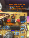
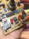
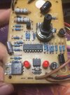
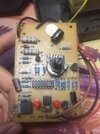
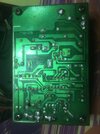
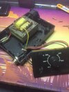
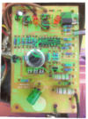
I have an old soldering station but sudenly 1 or 2 of the resistor burn but idont know how to read board or skematic, I just need the value of the resistor need to replace, I provide some picture link. so any one analize what is I am saying.

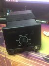
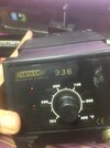
AEOLUS 936 Soldering Station (11yrs old i think)

Link google drive!
https://drive.google.com/drive/folders/1KmgO7BLfqEn7e28eUeNG0PYKBteJcTDR?usp=sharing

contact me if you need more picture of information about the soldering station
Jogene!!
 

Attachments

  • IMG_3045.JPG
    IMG_3045.JPG
    870.7 KB · Views: 277
  • IMG_3046.JPG
    IMG_3046.JPG
    1 MB · Views: 260
  • IMG_3048.JPG
    IMG_3048.JPG
    998.7 KB · Views: 256
  • IMG_3049.JPG
    IMG_3049.JPG
    1.5 MB · Views: 304
  • IMG_3050.JPG
    IMG_3050.JPG
    1.9 MB · Views: 288
  • IMG_3051.JPG
    IMG_3051.JPG
    937.3 KB · Views: 253
  • IMG_3052.JPG
    IMG_3052.JPG
    993.8 KB · Views: 291
  • IMG_3053.JPG
    IMG_3053.JPG
    1.6 MB · Views: 259
Here is manual, attached, schematic and values in it -

Regards, Dana.
 

Attachments

  • aoyue_936_soldering_station.pdf
    3 MB · Views: 338
Unfortunately not quite the right manual, but it certainly gives a decent idea of what's happening.

Presumably the resistor is R22 from the circuit, coupling from opto-triac to main triac. It's shown as 50 ohms, but has 47 ohms in the pictures in the manual, either would be fine, it's not critical, and 47 is a standard value.

However, the degree of burn-up is quite severe, so perhaps the main triac has failed?, or the opto-triac?, or both?.

I think I'd simply change all three.

The second resistor (not shown on the circuit) looks to be OK, and is just marked by the damage next to it.
 
The manual I posted is wrong manual. But looking at HAKKO 936 lot of similarities, and
many 3'rd parties cloning Hakko. If you google you an find more than one manual for
similar looking and schematics that have similar looking T control circuits. So maybe hand draw
that section of schematic and compare against others, might be able to hit on the right
part description. Also look at board layouts as clues.

My apologies medgard789 for not paying attention on prior post.

Regards, Dana.
 
Unfortunately not quite the right manual, but it certainly gives a decent idea of what's happening.

Presumably the resistor is R22 from the circuit, coupling from opto-triac to main triac. It's shown as 50 ohms, but has 47 ohms in the pictures in the manual, either would be fine, it's not critical, and 47 is a standard value.

However, the degree of burn-up is quite severe, so perhaps the main triac has failed?, or the opto-triac?, or both?.

I think I'd simply change all three.

The second resistor (not shown on the circuit) looks to be OK, and is just marked by the damage next to it.
I try testing it.
 
The manual I posted is wrong manual. But looking at HAKKO 936 lot of similarities, and
many 3'rd parties cloning Hakko. If you google you an find more than one manual for
similar looking and schematics that have similar looking T control circuits. So maybe hand draw
that section of schematic and compare against others, might be able to hit on the right
part description. Also look at board layouts as clues.

My apologies medgard789 for not paying attention on prior post.

Regards, Dana.
its ok, my soldering station is old, and I think my soldering station is only sale at my country (Phillipines) the brand AEOLUS
 
I check the board again and trace it at the back, and I notice 1 of the resistor is connected on the one of the LED (power indicator LED) its mean that 2 resistor is resistor for each LED, the one that burn is connedted to MOC3023 chip that controll the LED to blink/steady when in operation (2 LED = one is power indecator and the other one is heating indicator steady is heating and blinking is finish heating on the desire heat or maybe oposite/reverse I forgot lol)
 

Attachments

  • soldering pdb back miror.png
    soldering pdb back miror.png
    8.7 MB · Views: 304
  • IMG_3053.JPG
    IMG_3053.JPG
    1.6 MB · Views: 233
I check the board again and trace it at the back, and I notice 1 of the resistor is connected on the one of the LED (power indicator LED) its mean that 2 resistor is resistor for each LED, the one that burn is connedted to MOC3023 chip that controll the LED to blink/steady when in operation (2 LED = one is power indecator and the other one is heating indicator steady is heating and blinking is finish heating on the desire heat or maybe oposite/reverse I forgot lol)
As I said in post #3 - and also that it won't just be the resistor (they don't burn up for no reason) - you such change the triac and the opto-triac (MOC3023)
 
As I said in post #3 - and also that it won't just be the resistor (they don't burn up for no reason) - you such change the triac and the opto-triac (MOC3023)
I repalce the burn resistor and replace the jumper wire that burn and test the soldering station and work no magic smoke.
Now the Solering station working fine, I hope it will last long..
 
Status
Not open for further replies.

Latest threads

New Articles From Microcontroller Tips

Back
Top