Continue to Site

Welcome to our site!

Electro Tech is an online community (with over 170,000 members) who enjoy talking about and building electronic circuits, projects and gadgets. To participate you need to register. Registration is free. Click here to register now.

  • Welcome to our site! Electro Tech is an online community (with over 170,000 members) who enjoy talking about and building electronic circuits, projects and gadgets. To participate you need to register. Registration is free. Click here to register now.

Can a SIM program play the output sound of a bad amplifier circuit?

Status
Not open for further replies.

audioguru

Well-Known Member
Most Helpful Member
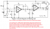
There is a hearing aid thread here that linked to a horrible circuit that would produce extremely high distortion.
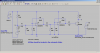
Without building it I would like to hear it and demonstrate how bad it is. I would like to feed the SIM program a WAV file of music and speech and have it play the output. Can LTspiceIV do it?
 

Attachments

  • bad hearing aid.png
    bad hearing aid.png
    245.3 KB · Views: 360
https://www.audio-perfection.com/spice-ltspice/distortion-measurements-with-ltspice.html
----------------------------------------------from Ron H.-----------------------------------------------------
If you use LTspice, you can use a .WAV file as in input, and then listen to the output of your simulation.
--------------------------------------------Below is from the LTspice help file:------------------------------------------------
.WAVE -- Write Selected Nodes to a .Wav File.


LTspice can write .wav audio files. These files can then be listened to or be used as the input of another simulation.


Syntax: .wave <filename.wav> <Nbits> <SampleRate> V(out) [V(out2) ...]


example: .wave C:\output.wav 16 44.1K V(left) V(right)


<filename.wav> is either a complete absolute path for the .wav file you wish to create or a relative path computed from the directory containing the simulation schematic or netlist. Double quotes may be used to specify a path containing spaces. <Nbits> is the number of sampling bits. The valid range is from 1 to 32 bits.
<SampleRate> is the number of samples to write per simulated second. The valid range is 1 to 4294967295 samples be second. The remainder of the syntax lists the nodes that you wish to save. Each node will be an independent channel in the .wav file. The number of channels may be as few as one or as many as 65535. It is possible to write a device current, e.g., Ib(Q1) as well as node voltage. The .wav analog to digital converter has a full scale range of -1 to +1 Volt or Amp.


Note that it is possible to write .wav files that cannot be played on your PC sound system because of the number of channels, sample rate or number of bits due to limitations of your PC's codec. But these .wav files may still be used in LTspice as input for another simulation. See the sections LTspice=>Circuit Elements=>V. Voltage Source and I. Current source for information on playing a .wav file into an LTspice simulation. If you want to play the .wav file on your PC sound card, keep in mind that the more popularly supported .wav file formats have 1 or 2 channels; 8 or 16 bits/channel; and a sample rate of 11025, 22050, or 44100 Hz.
***********************************************************

Syntax: Vxxx n+ n- wavefile=<filename> [chan=<nnn>]


This allows a .wav file to be used as an input to LTspice. <filename> is either a full, absolute path for the .wav file or a relative path computed from the directory containing the simulation schematic or netlist. Double quotes may be used to specify a path containing spaces. The .wav file may contain up to 65536 channels, numbered 0 to 65535. Chan may be set to specify which channel is used. By default, the first channel, number 0, is used. The .wav file is interpreted as having a full scale range from -1V to 1V.


This source only has meaning in a .tran analysis.
 
Hmmm. Kinda complicated. Thanks, anyway.
Maybe I don't wanna hear severe distortion anymore.
 
Here's the circuit AG is referring to.
Attached are .wav files of a 20 microV RMS 1kHz sine-wave tone used as input to the circuit, and the resulting distorted output from the circuit. Just delete the .txt extension to use them. Also attached is the .asc file, showing the syntax for .wav input and .wav output.
 

Attachments

  • Tones.wav.txt
    31.3 KB · Views: 142
  • tones_out.wav.txt
    172.3 KB · Views: 159
  • DistortionTest.asc
    3 KB · Views: 178
Here's the circuit AG is referring to.
Attached are .wav files of a 20 microV RMS 1kHz sine-wave tone used as input to the circuit, and the resulting distorted output from the circuit. Just delete the .txt extension to use them. Also attached is the .asc file, showing the syntax for .wav input and .wav output.

hi

The LM358 components are missing...:(

eT
 
I also cannot simulate an LM358 dual opamp.

Your "Tones Out" file sounds exactly the same as your "Tones (input)" file. But the output is supposed to be half-wave rectified by the opamps.
I want to hear the mess the circuit makes with speech and music that have continuously variable levels that will play nothing when the level is below the base-emitter voltage of the transistor.

EDIT: I think your circuit should use a 32 ohms resistor as its load instead of the low value extremely low resistance inductor.
 
I think your SIM program needs a hearing aid and some opamp theory.
Both non-inverting opamps have no input bias voltage so they rectify any input signal. Rectified audio is obvious on a 'scope and sounds awful.
The output of each opamp is the positive-going parts of the AC input signal. The transistor does nothing until its input voltage reaches about +0.65V.
 
The LM358 components are missing.
Sorry about that. See attached.
Your "Tones Out" file sounds exactly the same as your "Tones (input)" file.
Shouldn't do (if you've got your hearing aid switched on, AG :)). Here's a shot of an extract of the two waveforms, the latter showing rectification as expected.
ToneDistortion.gif
I think your circuit should use a 32 ohms resistor as its load instead of the low value extremely low resistance inductor.
The simulated load was a 10uH inductor with a series resistance of 32Ω!
 

Attachments

  • LM358NS.ASY
    782 bytes · Views: 138
  • LM358NS.sub
    2.8 KB · Views: 133
hi:)

I've added bias.
Here's a zip file with Alex_T schematic and the distorted wave file.

You'll have to manually run the wave file in Media player when the sim completes. (if you are using windows). Sim take a while...about 167 seconds on my fast computer.

eT
 

Attachments

  • DistortionTest1.zip
    5.7 KB · Views: 154
  • DistortedAmpCkt.png
    DistortedAmpCkt.png
    39.4 KB · Views: 208
Last edited:
You added some DC bias to the signal generator (why?) but not to the opamps.
In the original unbiased circuit I cannot see how the signal anywhere can swing negative as you show it at an output from something (from what and from where, what is B1?) when nothing has a negative supply voltage.
I think the output of each opamp normally swings positive up to about +1.8V but is close to 0V when the input swings negative.
Since the transistor also is not biased then its collector output will be just a narrow slice of the output of the second opamp when it swings from about +65V to about +75V.
 
In the original unbiased circuit I cannot see how the signal anywhere can swing negative as you show it at an output from something (from what and from where, what is B1?) when nothing has a negative supply voltage.
In the sim I posted, B1 is a 'behavioral voltage source'. I used it simply to scale and DC-offset the output voltage (across the 32Ω inductor modelling an earphone) to make it suitable for recording as a wav file.
 
You added some DC bias to the signal generator (why?) but not to the opamps.
In the original unbiased circuit I cannot see how the signal anywhere can swing negative as you show it at an output from something (from what and from where, what is B1?) when nothing has a negative supply voltage.
I think the output of each opamp normally swings positive up to about +1.8V but is close to 0V when the input swings negative.
Since the transistor also is not biased then its collector output will be just a narrow slice of the output of the second opamp when it swings from about +65V to about +75V.

I misunderstood...I thought at the mic input because dc is present there on the original crappy circuit. Aren't you wanting to duplicate the crappy circuit so it will reproduce a horrible sound?:confused:

eT
 
Last edited:
I thought at the mic input because dc is present there on the original crappy circuit.
The mic signal is AC coupled to the amp via a capacitor, so for small AC signals any DC bias at the mic does not contribute to the amp's distortion.
 
The original circuit used an electret mic which has a Jfet impedance converter that must be powered.
The inputs of an LM358 dual opamp are PNP transistors that still work perfectly when their DC voltage is the same as the negative supply voltage which is 0V in this circuit.
The input to the opamp swings positive and negative but since the opamps have no negative supply voltage and have their inputs biased at 0V, then the opamps do nothing and keep the output slightly more positive than 0V when the input swings negative thus the opamps are rectifying the signal.

The transistor is also not biased so its base-emitter "turn on" voltage is a threshold that waits for its input signal level to reach which makes the distortion much worse.
 
Agreed, the opamps and transistor all have a rectifying effect. I deliberately chose a very small input signal amplitude for the sim, which results in just the onset of clipping. Any larger input results in a more or less square-wave output. Despite the awful distortion, the output is still intelligible.
I would like to feed the SIM program a WAV file of music and speech and have it play the output. Can LTspiceIV do it?
Here you are, AG, as requested. Delete the .txt file extensions.
 

Attachments

  • Snatch_In.wav.txt
    580.2 KB · Views: 152
  • snatch_out.wav.txt
    290.2 KB · Views: 138
Your Snatch In sounds good and your Snatch Out sounds slightly lower in level but sounds the same.
I do not hear the severe distortion caused by the opamps half-wave rectifying the sounds and I do not hear the music parts missing when the output transistor has no bias.
 
Status
Not open for further replies.

Latest threads

Back
Top