Continue to Site

Welcome to our site!

Electro Tech is an online community (with over 170,000 members) who enjoy talking about and building electronic circuits, projects and gadgets. To participate you need to register. Registration is free. Click here to register now.

  • Welcome to our site! Electro Tech is an online community (with over 170,000 members) who enjoy talking about and building electronic circuits, projects and gadgets. To participate you need to register. Registration is free. Click here to register now.

Can 3 zener diodes and 1 resistor in series make many voltages?

Status
Not open for further replies.

mik3ca

Member
I was reading that a voltage regulator can be made with a resistor and reverse-biased zener diode in series in which the output is taken between the two parts and the other ends are connected to the power supply.

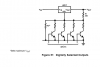
Would I be able to make reliable voltages and currents for programming a microcontroller with just a resistor and 3 zener diodes in series in which the diodes are all reverse-biased?
 
Yes, but you have to be careful with the amount of output current you draw from the string. All of the output current goes through the resistor and whichever diodes are "above" the output tap being used. If you draw out too much current, the voltage drop across the resistor increases until there is not enough voltage left across the diode string to properly bias it. So make a table of the output current at each tap, the voltage across each zener, and the max current for each zener (based on each diode's max power dissipation spec). Sketch up a schematic showing the powr supply, resistor, all diodes, and the load current at each tap, and post it here for review.

Note - for best reliability, derate app components by 50%. That is, if a zener diode is rated for 1 W, do not cause it to dissipate more than 0.5 W under any conditions. Same for the resistor.

ak
 
Last edited:
This is a very old way to make a digitally-selected voltage source:
upload_2017-12-23_18-18-11.png


Source: Datasheet for LM117-series voltage regulators.
 

Attachments

  • upload_2017-12-23_18-19-5.png
    upload_2017-12-23_18-19-5.png
    22.3 KB · Views: 92
Note - for best reliability, derate app components by 50%. That is, if a zener diode is rated for 1 W, do not cause it to dissipate more than 1.2 W under any conditions. Same for the resistor.

How is that derating?

Mike.
 
Ok, i think I'll go with the zener diode method. Pardon my diode drawing in my schematic, but I meant for them to be zener. I'm looking at making each diode and resistor 500mW. Idea here is one transistor will set the voltage to 5V if it is switched on (5V pin=logic high). If it isn't switched on, then if the second transistor is off, then output is 14V, otherwise its 12V.

I have a feeling i need to include some voltage drops in the transistors themselves to calculate the actual voltage being produced.

Also, is 1K for a resistor low enough? I want to use the circuit to program a w77e58 microcontroller and it requires 12V at vpp for programming and 14V for erase but I also want to give it 5V at vpp when I want it just in reset and doing nothing while in reset.

If my theory is wrong, can someone give me some math so I have something to work with?

circuit.png
 
Here is how I would do it:

ze.png
 
I'm trying to understand your design. So you have 3 diodes in parallel of which 2 are controlled by switches and 1 fixes the source to 14V? So if zener diodes were in parallel then the one with the lowest voltage rating will take precedence (meaning that's the output voltage)?
 
I'm trying to understand your design. So you have 3 diodes in parallel of which 2 are controlled by switches and 1 fixes the source to 14V? So if zener diodes were in parallel then the one with the lowest voltage rating will take precedence (meaning that's the output voltage)?

You got it, Toyota...

Zeners tend to be sloppy, so I would rather have the output voltage determined by one-at-a-time, rather than two or three in-series...
 
My experiment I did 2 seconds ago agrees with you. I just hooked up a 4.7K resistor and a reverse-biased zener in series. Voltage measured was 1.5V with a 1N5221B diode even though that diode is supposed to drop 2.4V? Maybe I'm better off using your circuit and replacing those diodes with voltage regulators
 
My experiment I did 2 seconds ago agrees with you. I just hooked up a 4.7K resistor and a reverse-biased zener in series. Voltage measured was 1.5V with a 1N5221B diode even though that diode is supposed to drop 2.4V?
You didn't read the datasheet. The 1N5221B is rated when its current is 20mA. If you used an 18V supply feeding the 4.7k resistor then its current was only 3.5mA so of course its voltage was low. It is the lowest voltage in that series so its voltage regulation is the worst.
Nobody makes a 2V or a 14V zener diode.
 
I must be better off using voltage regulators then. I'm wondering if I can switch the regulator on and off with the transistor between adj and gnd. hmm
 
04.png
 
I'm wondering if I can switch the regulator on and off with the transistor between adj and gnd. hmm
Why didn't you read the datasheet for the LM117/LM317? It shows that there is always 1.25V between the Adj and Gnd pins so if you ground the Adj pin the output will be +1.25V.
 
Oh I forgot about that but does that apply to all voltage regulators? If so, then I'm gonna just stick with resistors and zener diodes. and transistors
 
This is what I have come up with based on parts available:
circuit.png


and the bottom lines are ground (I don't know why the ground symbol got cut off. lol).

Could this circuit actually work if I choose the correct diode values and do I need to factor in transistor voltages when calculating the required voltage for the diode?

INB and INA will be directly connected to output pins of a shift register (74HC595)
 
Oh I forgot about that but does that apply to all voltage regulators? If so, then I'm gonna just stick with resistors and zener diodes. and transistors
You do not have a clue about fixed and variable voltage regulators. They are different and everything about them is in their datasheets.
Also, the datasheet of a low voltage zener diode shows that its voltage regulation is poor, but you saw that.
 
My goal here is to be able to produce 14, 12 and 5V for the vpp pin using two digital inputs.

I used a voltage regulator on left to provide 15V. then I use diodes and transistors to select a voltage. What may have confused people was that the 7805 output was connected to VCC but that VCC is actually the +ve power going INTO my circuit.I used my arrangement to not overheat the 7805.

So if I had 18 instead of 15V going into the 7805 (example: 7805 and 7815 in parallel) then thats +3v times current pull (less than 1A) = 3 watts of extra power needed right?
 
Status
Not open for further replies.

Latest threads

New Articles From Microcontroller Tips

Back
Top