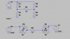
Show below are 3 solutions. The first solution is a mesh solution for the Vcc loop on the left side of the circuit. The second solution is a mesh solution for the Vcc loop on the right side of the circuit. The third solution is my method 2 suggestion from above showing a
node solution with a 1 amp current source applied to the Vcc terminal. The calculated voltage value of the third method is the same as the impedance because the current source is 1 amp. Better learn how to use these methods or you will wander around in a wonderland of perpetual fog. All the methods below use 3 equations and solve for 3 unknowns.
View attachment 114842
As you can see, the impedance is 685/24 ohms.
Ratch