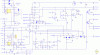
Continue to Site

Welcome to our site!

Electro Tech is an online community (with over 170,000 members) who enjoy talking about and building electronic circuits, projects and gadgets. To participate you need to register. Registration is free. Click here to register now.

  • Welcome to our site! Electro Tech is an online community (with over 170,000 members) who enjoy talking about and building electronic circuits, projects and gadgets. To participate you need to register. Registration is free. Click here to register now.

calculate resistor values.

Status
Not open for further replies.

yafch

New Member
Hello fellows,


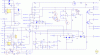
I,ve attached a pdf file containing the diagram of psu circuit. There are resistors in the circuit marked just "SEL". i think there value is left to be calculated according to application specific.
how can i get those values?
can some body give me the formula to calculate these values.

(the file is pdf formate i,can not mark those resistors because i dont know how to edit a pdf file please dont mind.)
 

Attachments

  • psu.pdf
    27.8 KB · Views: 390
hi,
Those values are chosen to to suit the DPM [digital panel meter] that you are using on the project.:)

Which DPM do you have.?

EDIT: a gif file of your pdf, you can edit this type.
 

Attachments

  • AAesp02.gif
    AAesp02.gif
    72 KB · Views: 412
Last edited:
here is the dvm that i,ll use here. it is the circuit most commonly avialable on the web.based on ICL7107.
 
Last edited:
thank you ericgibbs, for the gif image. i am posting it again with resistor and one capacitor circled. I am also attaching the wiring diagram for the psu schematics/board. this wiring diagram say two DPM,s with full scale settings at 200mv.
i can make those from the datasheet of ICL7107(intersil).As 7107 uses +5v and-5v so i will use famous 7660 for converting +5v to -5V(not a problem).
Now can you tell me how can i calculate those resistor values.
 

Attachments

  • wiring the psu..pdf
    159.3 KB · Views: 256
  • AAesp022.GIF
    AAesp022.GIF
    73.7 KB · Views: 956
thank you ericgibbs, for the gif image. i am posting it again with resistor and one capacitor circled. I am also attaching the wiring diagram for the psu schematics/board. this wiring diagram say two DPM,s with full scale settings at 200mv.
i can make those from the datasheet of ICL7107(intersil).As 7107 uses +5v and-5v so i will use famous 7660 for converting +5v to -5V(not a problem).
Now can you tell me how can i calculate those resistor values.

hi,
I have been working thru the two diagrams, but its almost impossible to read the pin numbers.
Can you post the complete pdf or a link to the design pdf source.?
 

Attachments

  • wiring1.gif
    wiring1.gif
    129.7 KB · Views: 897
Hi, sorry for late reply. i was away for work. two more files are attached here for clarification of the problem. one is parts placement on the board with parts names and the other is parts designatiors according to schematics.

thanks for your time.
 

Attachments

  • parts values..pdf
    77.7 KB · Views: 236
  • parts designators.pdf
    70.6 KB · Views: 225
Hi, sorry for late reply. i was away for work. two more files are attached here for clarification of the problem. one is parts placement on the board with parts names and the other is parts designatiors according to schematics.

thanks for your time.

hi,
Downloaded your files, give me a couple of days to reply, see what I can suggest.
I am assuming that the psu is designed to give 1Amp from 0V thru 24Vdc, can you confirm this.?
 
hi,
ericgibbs sir, you are right. it is 24v adjustable @0-1A power supply.

i may be wrong but i think the resistor values for dpm are voltage divider resistors to be connected at inputs of 7107 for adjustment of voltage measurement.but there are unknown capacitors,i marked one and forgot to mark another one.sorry.

i am much more thankful to you for the headache you took for me. i,ll be waiting till you figure it out.
thanks a million.

hi,
The resistors are for the voltage divider to suit the DPM in order to get the correct ranges, the cap is a simple filter for the signal.
 
now it is clear that those resistors are voltage dividers.
the problem is how can i figure their values.please keep in mind that the meters will be made according to the schematics in icl7107 datasheet.

i can wait till you figure them out, please.
 
now it is clear that those resistors are voltage dividers.
the problem is how can i figure their values.please keep in mind that the meters will be made according to the schematics in icl7107 datasheet.

i can wait till you figure them out, please.

hi,
I have spent quite some time trying to determine those values, at the moment there are two many unknown variables.
I need access to the full documentation for the psu.:)
 
hi,
sorry to say, but the files i posted here are all i have. No other file are available to me. i am thinking to use the meters at the outputs of supply as we do in simple projects. voltmeter at output and ammeter in series with load with a low ohm power resistor. what you say? thank you once again for your help.
 
Last edited:
Status
Not open for further replies.

Latest threads

New Articles From Microcontroller Tips

Back
Top