Continue to Site

Welcome to our site!

Electro Tech is an online community (with over 170,000 members) who enjoy talking about and building electronic circuits, projects and gadgets. To participate you need to register. Registration is free. Click here to register now.

  • Welcome to our site! Electro Tech is an online community (with over 170,000 members) who enjoy talking about and building electronic circuits, projects and gadgets. To participate you need to register. Registration is free. Click here to register now.

caculating wattage , db gain etc,

Status
Not open for further replies.
thanks now how to determine input

level (output of the PIC18F1320??
5v supply with a 10k resistor on the output = .0005ma
how large of a resistor to use to get more volume BUT the speaker is only .3w
I have currently 2 speakers from Mouser
665-AS02808MR2R sounds ok but more volume. currenty running using just a 2n2222. sounds just like when I connected the LM386

665-AT-1620-TWTR have yet to try out
 
Projects Unlimited do not make the speaker with the Mouser part number. They make an AS02808MR-R that is tiny, has a very low output level, has a max continuous power rating of 1W, is 8 ohms and has a response from 500Hz up.

The 2N2222 from a 5V supply will drive it with about 21mA DC pulses which are tiny noises, not audio.
An LM386 amplifier from a 5V supply will have an audio output of 0.14W at clipping or 0.28W max with a square-wave output.

How did you connect the speaker to the LM386?
 
I connected using a cap in series

Not real sure If I did the transistor right.
here is both ways I connected the output.both work but is it the best that I hope to get.
the LM386 circuit is going to be mounted on a vehicle to scare away deer from being hit by attached vehicle.
there is a product on the market (the Hornet) but it states it uses a 2-6khz as well as ultrasonic . It uses Wave Variance Tuning
The Physics of Sound (in other words BS)
my design uses basically same except it doesn't use ultrasonic which deer really don't hear anyway.
I believe the Hornet states it puts out 130db of sound (120 causes hearing loss)
there is a similar product that states basically same bs.
I need to test the circuit using the 665-AT-1620-TWTR.
this audio stuff throws me a curve.
 

Attachments

  • Capture5-17-2009-11.39.43 AM.jpg
    Capture5-17-2009-11.39.43 AM.jpg
    133.8 KB · Views: 102
  • Capture5-17-2009-11.38.42 AM.jpg
    Capture5-17-2009-11.38.42 AM.jpg
    152 KB · Views: 124
Peak Music Power is measured in Whats, not in Watts.
Little computer speakers are powered with a 12V/1A power supply (12W) and are rated for 1000 Whats.

i like that..... that explains the sony low-fi monster boom box systems with a 100 watt transformer that has "300W" plastered all over the box, and the advertizing blurb says "6000WATTS PMPO!!!!!!" it has two 50W amp chips in it for the woofers and a dual 30W amp chip for the tweeters..... (picture shown below)

they should change the term to"Whats" when they stretch the truth so far beyond the physics that it's unrecognizeable as reality. i guess the 6000W PMPO is measured in the microsecond before the amp chips let the smoke out during testing.......

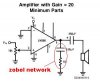
i think the OP's confusion is the LM386 having a gain between 20 and 200, and mistaking this for DB's. the gain is simply 20 to 200. dbs are sometimes used by some manufacturers for measuring op amp gain, when the gain of an op amp is in excess of 100,000. saying the gain is 50db takes up less space in print.

db measurements have a certain amount of confusion associated with them for most people, because there are so many different ways they are used. you have db, which is just a ratio, such as between input and output, you have dbV which is compared against 1 volt (including dbmV or dbu for 1 mV or 1 uV) for signal levels, or dbmW (sometimes written as dbm and dbW would db compared to 1 watt) for comparison against 1 milliwatt. you will sometimes see dbc, where harmonic content or noise is compared directly to a carrier level.

with audio you will see distortion measured in db, such as -70db. technically, this should be written as dbc, because it's compared against a signal level.

or you may see the sensitivity of a speaker written as db@1m, for instance 90db@1m which is the sound pressure level (SPL) measured 1 meter away from the speaker at 1W input. from this (and here is where Watts comes into the equation) you can calculate the SPL at any wattage within the capabilities of the speaker. so at 10W (10dbW), you get an SPL of 100db, and at 100W (20dbW) you get 110db SPL.

these are some of the ways that db measurements are used, and also why there is so much confusion about their use.
 

Attachments

  • sonymx8-2.jpg
    sonymx8-2.jpg
    4.1 KB · Views: 102
you need to ground the emitter of the transistor for it to work.
 
You have the pin 14 VDD pin of the PIC connected to -4.5V instead of +4.5V.

Of course the pin 5 VSS of the PIC and the emitter of the 2N2222 should be connected to 0V.
Then when the output of the PIC goes to +4.5V the 10k base resistor has 3.8V across it and its current is only 0.38mA which is the base current for the transistor. The output current of the transistor will be about 120 times more at 46mA. If the signal is a square wave then the 8 ohm speaker will have an average power of 0.004W.
If the base current is increased to 21mA (by reducing the value of the base resistor to 180 ohms) then the transistor's output current will be from 210mA to 420mA and the average power in the 8 ohm speaker is from 0.088W to 0.35W.

Your LM386 circuit is missing the important parts shown in the datasheet that keep it from oscillating at a high frequency.
 
Last edited:
.... which are the 0.05uf cap in series with the 10 ohm resistor..... also known as a Zobel network..... you must have these there to keep the LM386 from self destructing. actually you won't find many 0.05uf caps available (shows how old that schematic is) use a 0.047uf (47nf)....
 
10 ohm resistor??

I need to relook at the data sheet but never saw a cap in series with the 10k resistor.
I do have a cap in series w/ the speaker.
may decrease the 10k to 1k.
I don't want to kill the battery to fast.
the schematic I posted has been modified alot so I didn't include all the connections -- sorry
 
actually you won't find many 0.05uf caps available (shows how old that schematic is) use a 0.047uf (47nf)....

I was always under the impression that 0.05uF was the American way, whilst 0.047uF was the European way? - 0.05 makes a hell of a lot more sense to be honest.

Likewise potentiometers, 470K and 500K, with 20% tolerence what's the point of using 470 instead of 500?.
 
what about the 10 ohm resistor etc.

the .047 cap, resistor etc where to put?
I posted the correct schematic. used the same schematic as w/ LM386 but copied n pasted, edited etc.
 

Attachments

  • Capture5-17-2009-3.47.11 PM.jpg
    Capture5-17-2009-3.47.11 PM.jpg
    151.1 KB · Views: 101
The single transistor makes a very poor amplifier because the value of its base resistor is 55 times too high and the transistor does not have enough current gain.

The LM386 amplifier doesn't work properly because the 10 ohms (not 10k ohms) resistor in series with a 0.05uF capacitor is not connected from its output to ground as shown on its datasheet.
 
like this...... this keeps the LM386 from becoming an RF oscillator, and burning up as a result....
 

Attachments

  • lm386_zobel.jpg
    lm386_zobel.jpg
    12.1 KB · Views: 112
Status
Not open for further replies.

Latest threads

New Articles From Microcontroller Tips

Back
Top