Continue to Site

Welcome to our site!

Electro Tech is an online community (with over 170,000 members) who enjoy talking about and building electronic circuits, projects and gadgets. To participate you need to register. Registration is free. Click here to register now.

  • Welcome to our site! Electro Tech is an online community (with over 170,000 members) who enjoy talking about and building electronic circuits, projects and gadgets. To participate you need to register. Registration is free. Click here to register now.

building a speedo

Status
Not open for further replies.

bunghole

New Member
hi everyone.

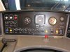
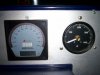
i need help building speedometer, based on the Innovonics model of a VLocity train in Victoria, Australia. The Bottom has a three digit, seven-segment speed display, and the outside has numbers around it, similar to an analogue speedometer, but instead of a needle, it has a series of LEDs on the outermost edge, which light up in 'bar' mode according to the speed. Between the two air gauges is the speedo, and the circular white line line are the individual LEDs.

thanks.
 

Attachments

  • vloc_1218_cab_centrepanel.jpg
    vloc_1218_cab_centrepanel.jpg
    160 KB · Views: 324
It's a speedo fever, if you look carefully at the schale you see the 0, 20, 40, 60 etc. km / h numbers on it.

Cheers, Ray
 
the two boxes below the speedo are the tacho. 'engine 1' is always the engine for the car that the cab is in. i know a bit about them because i was able to go to the factory on sunday mornings, and was able to move the trains around the factory yard. so i am probably the first 'public' person to set foot on these trains. (i am only 14, but went with my dad who worked there testinging them before the went into service)

I found a speedo project in another thread, using an at90s2313, so i can use that for a numerical display, but now i need a way to display the leds. if i can use two lm3914's coupled together, like fever's diagram, but constructed as a 12vdc voltage meter, and an adjustable frequency-voltage converter, i might have the thing done. but i need the meter and converter diagrams now.

Heres a different model of the speedo, but is on it's own. you can see then individual LED's in this picture, and this is the sort of speedo i'm trying to build, with a similar number of LED's. This is the 'new' speedo on comeng trains. (Worked with these trains too).
 

Attachments

  • 100_0418.JPG
    100_0418.JPG
    821.2 KB · Views: 209
Last edited:
Status
Not open for further replies.

Latest threads

New Articles From Microcontroller Tips

Back
Top