Continue to Site

Welcome to our site!

Electro Tech is an online community (with over 170,000 members) who enjoy talking about and building electronic circuits, projects and gadgets. To participate you need to register. Registration is free. Click here to register now.

  • Welcome to our site! Electro Tech is an online community (with over 170,000 members) who enjoy talking about and building electronic circuits, projects and gadgets. To participate you need to register. Registration is free. Click here to register now.

building a logic probe

Status
Not open for further replies.
samcheetah said:
i didnt get a word of what u said Nigel. okay i get the point that TRISTATE cannot be detected using TTL. so u give me a "CMOS solution" to my problem. but plz dont use any PICs :D

You couldn't do it with CMOS logic either, because it's not a logic state, either TTL or CMOS - the way to detect it would be to use two resistors across HT and ground (as I mentioned before) and a window comparator using a couple of opamps - the window comparator detects the input being half way between the supply rails, the two resistors force a tri-state rail to go to that voltage.
 
if TRISTATE isnt TTL compatible and it isnt CMOS compatible either then what is it compatible with??

im really confused. i thought this project would be a simple one.

listen guys i have heard of a book published by the ARRL. its name is "Build your own test equipment" by Carl J. Bergquist. i saw the table of contents of this book at a site and it has a tristate logic probe. now i cant find this book in my town. so please if someone has this book plz tell me how did the author of this book make the tristate logic probe
 
I think there was a bit of confusion, it's not the tristate he is after.
All he wants is to identify all possible signals:
- zero (TTL level less than 0.8V)
- one (TTL level higher than ca. 2.5V) and
- undefined or floating (level that is between 0.8 and 2.5V).

If so, maybe this link would help:

https://www.belza.cz/measure/logsonda.htm
 
Google returned following link as #1 hit for >tristate logic probe<
**broken link removed**

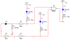
If you know how it works you will notice that uses same logic like
the previous link - it creates "tristate" signal if input is neither
zero nor one.

Using comparators as Nigel suggested would give you chance to
easily define "tristate window". The smaller the window, the higher
probe sensitivity. It's because even smaller current leaks would
disturbe the balance of the tip.

You are more than welcome to build it but I am not too convinced
that results would be as reliable as you might expect. More over,
you would have to look for special parts or sacrifice performance.
Maybe it's me but logic probe that cannot handle at least 20MHz
is not worth the trouble (unless you want to use it on something
as slow as LPT port). I didn't use comparators in a long time but
if I remember correctly, most of them used to be usable up to
one or max 5MHz. (on the other hand, things do progress fast so
who knows, your local Radio Shack might have inexpencive parts
that can handle 100MHz).

Here are some simple probes using OPs as comparators:
http://www.swansontec.com/sprobe.htm
**broken link removed**
 
Heres a link to a TTL logic probe i designed and built a few eons ago in which the high/low LEDs light up only when the probe is connected to the point under test ( that may be what Sam means by "tristate"). The circuit has the added advantage of displaying the letters "H" for high or "L" for low using a common 7-segment display.

http://www.geocities.com/nettron1000/LogicProbe.html
 
samcheetah said:
thanx all u guys. i built a logic probe and it works!!!!!. it tests a HIGH, LOW and a TRISTATE. im not sure about the loading effect it has and if it is workable at 20MHz.

anyway thanx again for all your help

How about posting the circuit?.
 
here u go

node 3 is the probe terminal
 

Attachments

  • probe.PNG
    probe.PNG
    8.5 KB · Views: 931
That's exactly what the other circuits do. What chips did you use and
what is loading?
 
i dont know about the loading effect the probe has on a test point that is being tested. i used a single 7400 IC because i needed 3 inverters and 1 NAND.

there is one slight problem though in this circuit. it doesnt work!!!!! (as such)

i took the idea for this probe from

**broken link removed**

in which the designer of this probe used a high resistance instead of the diode i used. by using a diode this certainly doesnt work. but when i thought of using a diode instead of a resistor i couldnt find one near me. so i used an LED instead and the probe worked. now when i got a diode and connected the whole circuit it doesnt works. but if i reconnect the LED the circuit works.

can somebody solve this mystery
 
samcheetah said:
if TRISTATE isnt TTL compatible and it isnt CMOS compatible either then what is it compatible with??

im really confused. i thought this project would be a simple one.

listen guys i have heard of a book published by the ARRL. its name is "Build your own test equipment" by Carl J. Bergquist. i saw the table of contents of this book at a site and it has a tristate logic probe. now i cant find this book in my town. so please if someone has this book plz tell me how did the author of this book make the tristate logic probe

I have the book, and the circuit that I posted on the first page of this thread is the same as inside the book (redrawn).
 
Status
Not open for further replies.

New Articles From Microcontroller Tips

Back
Top