Continue to Site

Welcome to our site!

Electro Tech is an online community (with over 170,000 members) who enjoy talking about and building electronic circuits, projects and gadgets. To participate you need to register. Registration is free. Click here to register now.

  • Welcome to our site! Electro Tech is an online community (with over 170,000 members) who enjoy talking about and building electronic circuits, projects and gadgets. To participate you need to register. Registration is free. Click here to register now.

Buck converter to charge LiPo

Status
Not open for further replies.
I am doing a project to turn an RC car into an obstacle avoiding robot.

The bot will be powered from a permanently installed single cell 1Ah Lithium Polymer battery.

I want to have a buck converter built into the car to charge the LiPo battery with at least 1A.

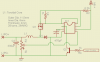
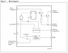
I'm using a MC34063ECN SMPS chip [datasheet] and want to power it from a 16VDC 4A regulated wall-wart.
I plan on using a PFET in the final circuit but am testing it with a PNP for the time being.

The circuit is easy enough to construct but I am unsure how to implement an output current limit as the max current must be limited in the first step of the charging cycle.
 

Attachments

  • diagram.png
    diagram.png
    19.4 KB · Views: 356
  • block.png
    block.png
    33.6 KB · Views: 202
use a chip dedicated to charging them. you are putting yourself and your bot at risk and you will end up spending more money on your hack than you would on a proper charging chip.
 
Hi there,


Couple of things to note here.

First, we dont know the inductance of your inductor. This is a problem because we would like to be able to calculate the ripple voltage, or at least estimate it. We want to do this because there is an issue that comes up when charging batteries like these with a switching power supply type charger, and that is that the ripple voltage should not push the output voltage above the 4.250 voltage limit of the cell. Really though, 4.200v is a better limit that should be imposed (assuming your cell is a 4.200v max type cell).

Second, that chip you selected unfortunately produces higher output ripple than most regulator chips. The reason for this is because it is based on a digital regulating principle rather than the more conventional analog method. The digital regulation is much different than analog, and the byproduct of this is more output ripple for the same filter component values. The only way around this is to make the inductor larger than usual. For example, maybe 1000uH rather than 100uH might accomplish this, but the final design needs to be tested to make sure it does not take the cell voltage above 4.200 volts at any time. Unfortunately we can not calculate the inductance of your inductor without knowing what kind of material the core is made of, so you are better off testing the design rather than trying to estimate the inductance, unless of course you want to try to measure it but an inductance meter probably wont show the true inductance for this kind of inductor so you should use a scope instead.

Third, if you are going to charge at 1 amp with a 4v output and you have a 16v input then theoretically you only need one quarter of the input current. That's because a buck converter is a true power converter so if you put in 4 watts you can get 4 watts out even if it is at a different voltage. Because of inefficiencies however, you'll need a little more input power than output power, but if the design is set up right you can easily get away with a 16v at 0.5 amp dc wall wart and you should easily get 4.2v at 1 amp output. This of course means you dont need such a heavy duty wall wart rated for 4 amps. This also means we get a little bit of 'hard wired' current protection for free.
 
Last edited:
How are you limiting the charging voltage to 4.20V? It will catch on fire if charged higher than 4.20V.
How are you detecting the current drop when the cell is fully charged so the charger turns off? The cell will be damaged and might catch on fire when over-charged.
 
I didn't want to use a dedicated chip as most of them are linear in function and ones that aren't are usually expensive.

As for the inductor, I do not know the permeability of it as I pulled it from the motherboard of a dead game console.
I am testing it on a breadboard with a 1A dummy load and hovered around the 4.15v with a change of about 10mV after warming up.

The voltage it limited through the voltage divider (R3) connected to the voltage sense (pin 5).

Since the µC will be powered directly from the battery I can sample the voltage every now and then to make sure it's still within the voltage range.

What I am stuck at is how to limit the initial current and continue to sample the current to detect the end of charge.
 
Hi,

Are you seeing a big inrush current to the cell?

To sample the current you can probably measure across the current sense resistor with an amplifier or you might use a current sensing chip. If your input voltage is relatively constant you may be able to set the current limit via the current peak set resistor. You'd have to test and see what works by increasing or decreasing the value and testing with a cell mostly depleted like around 3v or so.
There are some really nice amplifier chips out there with very low offset that work nice for current sensing through existing or added low value resistors like 0.1 ohms.
 
Status
Not open for further replies.

Latest threads

Back
Top