Continue to Site

Welcome to our site!

Electro Tech is an online community (with over 170,000 members) who enjoy talking about and building electronic circuits, projects and gadgets. To participate you need to register. Registration is free. Click here to register now.

  • Welcome to our site! Electro Tech is an online community (with over 170,000 members) who enjoy talking about and building electronic circuits, projects and gadgets. To participate you need to register. Registration is free. Click here to register now.

Buck Boost with Output 12V

Status
Not open for further replies.

abbasmacho

New Member
Hello. I am designing a circuit which is buck boost circuit. The problem is that when I design with Low-Cost Step-Up/Step-Down Converter Accepts 2V to 16V Inputs. The output current is too small. So I am planning to insert it the previous post design from audioguru

500w-inverter-final-png.22833


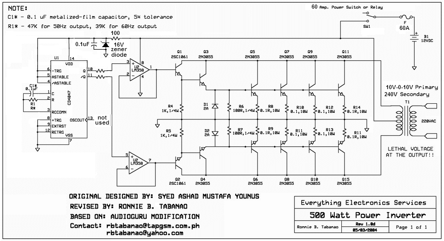
combining with this circuit. But the problem is the current is too small.

**broken link removed**

So the specification of the design should have input with 2V-16V and will produce output of 12V with minimum current of 2Amp. Is there any design using MOSFET or IGBT for the buck boost circuit.

Help is much be appreciated. Thank you.
 
Firstly, your circuits are boost circuits.
Secondly, why don't you use a pair of MOSFETS instead of all those 2N3055's.
Thirdly, how are you going to get 12v @ 2 amp from a 2v input, using the diode shown in the circuit?

How does an inductor have a value 18uF?

How are you going to turn on the transistor with 3k and 2v supply?

How are you going to drive 5 -- 2N3055's with 0.5v?

None of the circuits make any sense.
 
Last edited:
The first circuit is the inverter circuit. Which is the circuit that is going to produce 240Vac from a 12Vdc input. Diode in the circuit is used to prevent voltage spike from happen.

So the second circuit is the buck boost circuit with a range of 2-16Vdc input with output of 12Vdc. After set the value for R1, R2, R3 and R4 in order to achive the 12Vdc output. But the problem is the current is too low at only 500mA. It cannot drive the inverter circuit with low current.

I had test the inverter circuit with a battery with 1.2Ah. And it is working.

The inductor should be 18uH. Sorry for that.

The transistor is driven by 12Vdc supply. From the buck boost circuit.
 
Last edited:
You can't drive the top circuit from the bottom circuit.
The top circuit needs a very high current for a short period of time and you will need a very low impedance power supply to drive it. That's why a 12v battery is needed.
 
So do you have any buck boost circuit that can drive the top circuit. I know that the bottom circuit can't be possible to drive the above circuit. :)
 
Last edited:
I would say use just a boost circuit as the first stage, and modify the inverter so it's input is the maximum voltage input for the entire system.

That is, if you want 16v maximum input, then modify the invert to run at that voltage, and make 16v the output of the boost converter.

But, as colin said, a 12v - 500w inverter is going to pull a LOT of current, so trying to boost 2v to 16v is going to be way too impractical. Do the math on it
 
Last edited:
what sort of power source are you thinking of using that is 2 volts to 16 volts and still puts out 500 plus watts over that entire range?
 
Buck converter is the only thing that would work practically at that power.
 
Actually I'm designing a concept circuit that can produce optimum power using any input voltage. Which is in any range of input voltage applied the output is still the same.
 
Last edited:
ok, first a little bit of math, because there's no such thing as a free lunch.

the top circuit requires 12V @ 60A, so to supply this using a boost converter with 2V input would require 2V @ 360A (and that's assuming 100% conversion effeiciency which isn't possible). good luck finding mosfets and diodes for the 2v to 12v converter in that current range. ok, let's assume an 80% conversion efficiency. 360/0.8=450A actually required at 2V to get 12V@60A. you will need 1000mcm wire for the 2V circuit, that's about 1/14" (3cm) diameter wire. you will need switching mosfets rated at 500A and schottky rectifiers rated at 500A. the coil will need to be wound with at least 0000ga wire, just the copper, transistor and diode are going to be several hundred dollars US. 12V batteries are a lot cheaper (a new car battery costs about $40.00US).

so you have to keep in mind the rule of conservation of energy.
watts out= watts in * efficiency.
if you convert down in voltage, the current goes up.
if you convert up in voltage the current goes down.
you always have losses, and they must be compensated for at the input.


the only device i have seen that can source hundreds of amps at 2V was a laboratory power supply that was used for calibrating ammeters. it weighed about 500 pounds. other than that, maybe a bunch of single cell lead acid batteries wired in parallel. again, a lot of weight
 
If your going for optimum performance that inverter design schematic is the last thing you would want to use!
It is possible to build a universal voltage inverter that could run on anything from 6 to 24 volts but like unclejed613 pointed out the copper wire and switching devices get nuts big to do it at lower voltages.
At 6 volts your input would be around 130 amps and that is doable with standard mosfets and 0 ga wire. building the inverter to use a PWM circuit would allow it to compensate for the different voltage inputs on its own.
Plus with PWM circuits you have output voltage feed back to control it and get better line voltage regulation.
This still can be done with a 50-60 cycle transformer and with the right output filtering you can actualy get a reasonable looking sine wave too.
But the inverter however will be rather heavy!
 
Last edited:
Status
Not open for further replies.

Latest threads

New Articles From Microcontroller Tips

Back
Top