Continue to Site

Welcome to our site!

Electro Tech is an online community (with over 170,000 members) who enjoy talking about and building electronic circuits, projects and gadgets. To participate you need to register. Registration is free. Click here to register now.

  • Welcome to our site! Electro Tech is an online community (with over 170,000 members) who enjoy talking about and building electronic circuits, projects and gadgets. To participate you need to register. Registration is free. Click here to register now.

buck boost converter

Status
Not open for further replies.

muhammaduzair

New Member
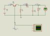
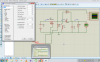
This the buck boost circuit but it is not working.by changing duty cycle no change in output voltage.can any body help me with this.Or providde me with a working proteus model of buck boost or CUK converte.I want to use it in MPPt solar chrge controller.
 

Attachments

  • buck boostnew.jpg
    buck boostnew.jpg
    167.1 KB · Views: 192
  • buck boost.jpg
    buck boost.jpg
    128.4 KB · Views: 205
Try reversing D1.

Welcome to the forum.
 
You say you have changed things and measured things, but you have not given us any information at all.
What is the output voltage you want?
What is the duty cycle you designed for this output?
What are the duty cycles and output voltages you are seeing?

The diode orientation is correct.

ak
 
I think the drive to the switching device needs to be floating and referenced to the source of the mosfet or the emitter of the transistor. You do not show what is referenced to so I assume it is to ground. The emitter / source needs to be able to go negative with respect to ground. If the drive signal never goes below ground then the emitter cannot go more negative than about 0.7 volts and the source cannot go more negative than the threshold voltage.

Les.
 
The FET needs to be P-channel with the drain connected to the inductor, and the BJT needs to be PNP with the collector connected to the inductor. With those changes, the drive signals can be common-grounded to the input.

ak
 
Thankx for your kind replies.I need input from 7 to 18 and output in range 5 to 30. I want to use converter to implement perturb and observe algo for MPPT charge controller.The problem with circuit is that its output do not change by changing duty cycle. i think this image will help you.
 

Attachments

  • upload_2016-2-18_10-31-33.png
    upload_2016-2-18_10-31-33.png
    191.1 KB · Views: 165
Last edited by a moderator:
I will try another way to explain what is happening.
The MOSFET turns on/off when voltage is applied from GATE to SOURCE. Because source is not at ground you will have a problem.
When the MOSFET is on the source is at 12V (input voltage) To keep the MOSFET on you will need to have (12+15) =27 volts on the gate, as referenced to ground.
The MOSFET, when off the source will be at (vout-0.7) volts. So at 50% duty cycle you will need a gate voltage of -13 volts or more negative.

upload_2016-2-18_6-11-55.png

I do not know your SPICE program. In LTSpice you connect a signal source from Gate to Source and do not connect it to ground.
Set the Frequency to 100khz.
On voltage to 15 volts and the off voltage to 0 or -5 volts.
When looking at voltages, I can see (gate-source) and see the +15 to 0 volts. When looking at gate to ground the wave form is complex.

Hope this helps.
 
You can drive the gate of the fet with a gate drive transformer.
 
In many SPICE programs there is a "switch" which can work much like a MOSFET.
The switch part is open or closed and the control part is totally isolated from the switch.
Note V1 is a signal source like a square wave generator.
upload_2016-2-18_7-10-41.png
 
Status
Not open for further replies.

Latest threads

New Articles From Microcontroller Tips

Back
Top