Hi,
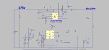
The attached circuit is NOT OK due to the negative voltage of TS w.r.t GND.
Howcome it cant take such a neg voltage?....
(LTspice and jPeg scm attache)
2ED2182S06
https://www.infineon.com/dgdl/Infin...N.pdf?fileId=5546d4626cb27db2016cb8d7368a29e3
LTC4440
https://www.analog.com/media/en/technical-documentation/data-sheets/4440fb.pdf
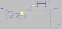