Continue to Site

Welcome to our site!

Electro Tech is an online community (with over 170,000 members) who enjoy talking about and building electronic circuits, projects and gadgets. To participate you need to register. Registration is free. Click here to register now.

  • Welcome to our site! Electro Tech is an online community (with over 170,000 members) who enjoy talking about and building electronic circuits, projects and gadgets. To participate you need to register. Registration is free. Click here to register now.

boosting current in a lm317t with a darlington transistor

Status
Not open for further replies.
I wouldn't use a Darlington. To preserve the overcurrent/overtemperature protections built in to the 317, you want it to deliver most of the current it is capable of. For example; if you want 5A, set up the 317T to deliver ~1A, while the bypass PNP transistor delivers ~4A. To do that, select the Emitter to Base resistor so that the drop across it is ~0.65V at the desired 317T current.

The Power calculation in the resistor goes like this: P =E^2/Rb, where E=0.65V
 
Last edited:
I wouldn't use a Darlington. To preserve the overcurrent/overtemperature protections built in to the 317, you want it to deliver most of the current it is capable of. For example; if you want 5A, set up the 317T to deliver ~1A, while the bypass PNP transistor delivers ~4A. To do that, select the Emitter to Base resistor so that the drop across it is ~0.65V at the desired 317T current.

The Power calculation in the resistor goes like this: P =E^2/Rb, where E=0.65V

Ah ok ... my reason for wanting to push all the current through the transistor is I have limited space to work with and can only fit one heatsink ... but I can always then as you say use the features of the LM317T without a heatsink to push say 500-1000ma, I must just see when exactly it cuts out.

could you let me know which fundamental I should read up on to try understand the above power calculation better? I was looking at ohms law Resistance = Difference in Voltage / Current , so Resistance = 0.65v / 1A = 0.65 ohm ... but I"m not sure if thats right.
 
Here is a typical application. Note the power dissipation in the resistor, the PNP and the LM317. Note also the voltage regulation, and the relative currents through the PNP and LM317.
 

Attachments

  • BR1.png
    BR1.png
    16.3 KB · Views: 4,218
  • BR2.png
    BR2.png
    34.1 KB · Views: 1,188
Ok, so the 1 ohm resister both creates a voltage differential between base and emitter to turn on the transistor AND ant the same time limits the current flowing through the LM317?
 
Ok, so the 1 ohm resister both creates a voltage differential between base and emitter to turn on the transistor AND ant the same time limits the current flowing through the LM317?

Yes to the first part; no to the second. Look at the Brown and Red Plots which show the currents through the PNP and the 317, respectively. The value of R5 (and the Hfe of the PNP) is what determines the ratio of Ic(Q2) to I(X). Note the sum of the two currents is the load current.
 
Yes to the first part; no to the second. Look at the Brown and Red Plots which show the currents through the PNP and the 317, respectively. The value of R5 (and the Hfe of the PNP) is what determines the ratio of Ic(Q2) to I(X). Note the sum of the two currents is the load current.

Ok. I'm trying to understand the math behind it now.

1. How did you know 1 ohm would cause the voltage differential because I'm very sure my calculation of 0.65 ohm is wrong.

2. Also how did you know 1 ohm would limit the lm317t to 1A? this is maybe part of the question of how did you calculate the 1 ohm as a ratio?
 
I simulated the circuit as shown. I varied R5 until I saw roughly 1A(317) and 4A(PNP) at the right side of the plots. The ratio of the currents is a function of the PNP type, the resistor, and the temperature. The Vbe of a power transistor is more than 0.65V when Ic gets up toward 4A. You would have to look in detail at the PNP's data sheet to get an accurate value.
 
Ok, excellent.

Is there a way to mathematically work out the wattage of R5? or does that bring me to the ohms law formula?
 
Well, when the current into the LM317 is 1A, (ignoring the base current of the PNP), that implies P = (I^2)*R = 1*1 = 1W, so use a 2W resistor.
 
Awesome.

I was looking at the datasheet now, under Absolute ratings it shows that the base current is 7A ... should I take this into account aswell?
 
That is the absolute maximum. During operation, the base current is the collector current Ic divided by hfe, which should be about 50, so 4/50 = 80mA
 
Cool.

How would I work out how much heat I need to dissipate in the LM317? is it a factor of current flowing through it vs. the voltage differential between in and out?
 
Cool.

How would I work out how much heat I need to dissipate in the LM317? is it a factor of current flowing through it vs. the voltage differential between in and out?

Toyota! (You got it)
 
which would make a higher voltage to a lower voltage pretty high wattage. So , take 20v down to 5v, pulling 1A.

so ... if I'm right, to find the resistance can I use ...
R = V / I = (20 - 5) / 1 = 15 / 1 = 15 ohm?

Can I then use your formula.. P = (I^2)*R
P = (I ^2) * R = (1 ^ 2) * 15 = 1 * 15 = 15 watt?
 
Yep, now do the calculation as to how many square inches (square cm?) of black aluminum it takes to get rid of 15W.

You can do the regulator dissipation more directly: P = I*E = Iload * (Vin-Vout) = 1 * ( 20-5) = 15W
 
Last edited:
Yep, now do the calculation as to how many square inches (square cm?) of black aluminum it takes to get rid of 15W.

You can do the regulator dissipation more directly: P = I*E = Iload * (Vin-Vout) = 1 * ( 20-5) = 15W

Awesome.

1. Now , on the heatsinks they have a rating of 3,5K/w ... how would I see how many W of power generated by a regulator that can dissipate? is it 3,5 or is there a more complex calculation?

2. How would one work out the amount of heat dissipated by the power transistor in my circuit?
 
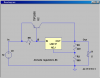
First, the power transistor has ~ the same voltage across it as the 317, except that it has 4A flowing through it, so (20-5)*4 = 60W.

If your heat sink's thermal resistance is 3.5 degC/W, then with 75W, the temperature of the heat sink would be 25degC (ambient temperature) + 3.5*75 = 25 + 262degC = 287degC, which is way, way too hot.

The max temperature you want at the heatsink is ~85degC (still hot enough to burn your hand). Starting from a 25degC ambient, that would mean that the temperature rise of your sink above ambient would have to be 85-25 = 60degC. Since you are dissipating 75W, the thermal resistance of the sink would be 60degC/75W or 0.8degC/W, which you will find will require like 4000cm². Are you convinced that this is dead end, yet?

This is not the way you should be doing this! To get 5V * 5A = 25W to the load, you are dissipating 60+15=75W in the regulator. This is where you should be using a buck switch-mode regulator. Alternatively, start with a different transformer so that the unregulated voltage is much closer to 5V.
 
Last edited:
Status
Not open for further replies.

Latest threads

New Articles From Microcontroller Tips

Back
Top