Continue to Site

Welcome to our site!

Electro Tech is an online community (with over 170,000 members) who enjoy talking about and building electronic circuits, projects and gadgets. To participate you need to register. Registration is free. Click here to register now.

  • Welcome to our site! Electro Tech is an online community (with over 170,000 members) who enjoy talking about and building electronic circuits, projects and gadgets. To participate you need to register. Registration is free. Click here to register now.

Boost Low Frequencies

Status
Not open for further replies.

Suraj143

Active Member
This is my second AMP build.Making an amp with tone control part.But it needs to boost the Bass frequency while gaining the input feed signal.

My main points are below.

1) When the BASS boost SW is OFF will it maintain the input signal gained? Because my Signal Inputs are weak, MP3 kits (chinese ones) & mobile phone outputs.
2) Will the 1st opamp pass the HIgh frequency as well? Because for the tone control it needs all the hearing frequencies.
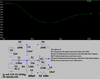
3) What will be the lowest frequency can pass from this circuit?

Will this circuit fullfill my above requirements?
 

Attachments

  • Low Freq Boost.JPG
    Low Freq Boost.JPG
    42.8 KB · Views: 330
That is not a bass boost circuit. If anything, it is a very poor bass-cut circuit.

Everything to the right of OP1 is a standard set of treble and bass tone controls like you see on most home stereo amplifiers. You can turn up the bass, but there is no switch.

The left circuit is a rumble filter. This is something good amplifiers have that is used with a turntable (record player) input. This one **cuts** bass frequencies below 7 Hz when the switch is closed. The idea is that the turntable platter bearings add a very low frequency vibration to the movement of the record under the needle, and this shows up in the audio signal as a very low frequency (rumble) sound.

To build a true bass-boost circuit, you must know two things before you start:

1. Which frequencies do you want to boost?

2. How much do you want to boost them?

Example: I want to boost all frequencies below 400 Hz by 10 dB.

With that information, we can help.

ak
 
Great Info.Thanks.

Actually I wanted to build a loudness circuit.Nowadays there is no 4 pin potentiometers(Mono) for loudness tap.So I wanted to do it from a circuit using standard potentiometers. I searched loudness circuits all over the net, but all are using old 4 pin potentiometers which is not available nowadays.

So I shifted to a BASS boost circuit instead.

Your example is correct for me.I want to boost all frequencies below 400 Hz .But the gain I do not know.

My final target is to listen to low volume with more BASS.
 
Working with the circuit you already have, make these changes:

1. Place R3 and R5 in series between the output and inverting input.

2. Place the switch and C2 in parallel withR3 (three parts in parallel).

To start, make both R3 and R5 = 47K. With the switch closed (non-boost), the circuit gain is unchanged from before, unity and inverting (47K / 47K). With the switch open, the impedance of the R3-C2 combination changes with frequency. At low frequencies, C2 is essentially open and the circuit gain is 2, a 6 dB bass boost. At high frequencies C2 "shorts out" R3 and the circuit is back to unity gain.

The ratio of R2 to R5 sets the amount of bass boost, and The combination of R3 and C2 sets the corner frequency when boosting starts. Having the two resistors in series sets a limit on the amount of bass boost no matter how low the frequency. This is sometimes called a shelf equalizer, because the frequency response plot has a flat top.

ak
 
Suraj, please learn the simple formula of opamp gain and of an RC cutoff frequency.

1) The series RC with a switch in the negative feedback of an opamp cuts frequencies above the RC cutoff frequency.
The gain without the RC is 47k/47k= 1. The gain with the 1M parallel with the 47k feedback is 44.9k/47k= 0.96 which is almost no difference.

2) The formula for the cutoff frequency of an RC is 1 divided by (2 x pi x R in ohms x C in Farads.
Then the cutoff frequency of 33nF and 47k is 103Hz and the cutoff frequency of 1M and 22nF is 7.3Hz.
 

Attachments

  • bass boost.png
    bass boost.png
    46.2 KB · Views: 244
Your copy is wrong. The circuit I posted in your other thread had the first opamp with a 1uF input capacitor feeding a 100k resistor producing a cutoff frequency of 1.6Hz so all the low frequencies would be completely level.

If you boost levels +12dB then the amplifier power must be 8 times more. Can your amplifier do that?

I modified your bass boost circuit of you want it anymore.
 

Attachments

  • bass boost corrected.png
    bass boost corrected.png
    21.7 KB · Views: 255
Your copy is wrong. The circuit I posted in your other thread had the first opamp with a 1uF input capacitor feeding a 100k resistor producing a cutoff frequency of 1.6Hz so all the low frequencies would be completely level.

If you boost levels +12dB then the amplifier power must be 8 times more. Can your amplifier do that?

I modified your bass boost circuit of you want it anymore.
Thank you very much as always.

You are correct, I have used a wrong copy.Sorry on that.I'm still new to OP Amps.
Your simulation is ok for me.I'm not sure what is 3dB.I guess it is double the power from the input signal..!!!

Below are my main concerns.

1)Can I place the boost ON switch across the C3 cap?
2)When no boost (Switch open) I need a little bit gain.Because my input signals are weak.(like mobile phones etc...)
3)Do I need a 100K parallel resistor before the 220nF cap (between the signal line & Gnd) ?

Is my diagram ok?
 

Attachments

  • 3.jpg
    3.jpg
    435.1 KB · Views: 238
Last edited:
Yes, 3dB is half or double the power. Since the sensitivity of out hearing is logarithmic, it sounds only a little less loud or a little louder. 10 times the power sounds twice as loud.
Your boost switch is correct.
If all your input levels are low then you can add gain by reducing the value of R3 and increasing the value of C2. But if a signal is higher then the added gain plus the boost might cause severe clipping distortion and a volume control at the input is needed
R6 prevents a POP sound when the input cable is connected. R6 is not needed of the input cable is always connected.
 
Last edited:
Ok Thank you very much.I will make the circuit & check.I'm not sure whether I need a little bit of Treble boost or not...!!!

In your home setup are you doing a simillar thing...!!!
 
In my home setup I never use tone controls and I built a bass boost circuit so that my 8" woofers sound and feel like a 12" sub-woofer.
Here is my bass-boost circuit, sorry I did not write my parts values:
 

Attachments

  • Bass extension circuit.png
    Bass extension circuit.png
    69.5 KB · Views: 273
Hi AG, I built the circuit in your post 7 & its works great. After boosting I cannot volume up my amp. Its too much bass. So the amplifier is clipping.

Is there anyway to get a small treble pickup along with the bass boost? Can I parallel another cap across the 15nF which will response to high's...!!

Reduce the value of R2 to reduce the bass boost.
 
I reduced the amount of bass boost and added some treble boost. I show which part does what.
 

Attachments

  • bass and treble boost.png
    bass and treble boost.png
    33.2 KB · Views: 225
Hi AG,

I built a PCB & did some changes in the Boost circuit values.In this the overoll gain is 1.47 Times the Input signal (Because I wanted a little gain in entire design).

I noticed that when the entire gain is higher then the boost is unnoticable :( Is this true?
 

Attachments

  • Boost Test.JPG
    Boost Test.JPG
    191.2 KB · Views: 204
Hi AG,

I built a PCB & did some changes in the Boost circuit values. In this the overall gain is 1.47 Times the Input signal (Because I wanted a little gain in entire design).

I noticed that when the entire gain is higher then the boost is unnoticeable :( Is this true?
Your 12V power supply voltage limits the maximum output signal level to about 5V peak. If the input is 1V and the bass boost gain is 220k/47k= 4.68 times then the output has a peak of almost the 5V where clipping will occur.

Then of course if you turn up the input level, the bass boost is clipping and cannot increase any more.
Clipping causes severe distortion.

EDIT: Do you have huge speakers that can play 25Hz?? If your speakers cutoff frequencies below 100Hz then your circuit will make them sound almost like normal speakers that have no bass boost.
 
Last edited:
EDIT: Do you have huge speakers that can play 25Hz?? If your speakers cutoff frequencies below 100Hz then your circuit will make them sound almost like normal speakers that have no bass boost.

You got it.I have small speakers 6.5" Sony Speakers.I have attached it spec sheet.Can you help me to fine tune the values to give a good bass boost on these speakers. Thanks
 

Attachments

  • Sony.JPG
    Sony.JPG
    110.8 KB · Views: 188
Your Sony speakers have no detailed specs. It says the "effective" frequency range without saying if it is +/- 2dB or if it is +/- 40dB.
I have some speakers I made using high quality woofers and tweeters. The woofers are low resonance 6.5" and I designed ported enclosures for them that makes them produce pretty good bass without needing bass boost.
 
Your Sony speakers have no detailed specs. It says the "effective" frequency range without saying if it is +/- 2dB or if it is +/- 40dB.

They are cheap crappy speakers, and in my (considerable) experience the drivers in those '160W speakers' probably only have 10W or 20W stamped on the back of the bass units. I've repaired a LOT of Sony speakers both in and out of warranty, they aren't generally much good.
 
Status
Not open for further replies.

Latest threads

New Articles From Microcontroller Tips

Back
Top