Continue to Site

Welcome to our site!

Electro Tech is an online community (with over 170,000 members) who enjoy talking about and building electronic circuits, projects and gadgets. To participate you need to register. Registration is free. Click here to register now.

  • Welcome to our site! Electro Tech is an online community (with over 170,000 members) who enjoy talking about and building electronic circuits, projects and gadgets. To participate you need to register. Registration is free. Click here to register now.

Boost converter - how it works.

Status
Not open for further replies.

alphacat

New Member
Hey, I wanted to ask a few questions please regarding Boost Converter.

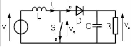
1.When the switch is close, the current increases linearly.
When the switch opens, the inductor's voltage jumps from zero to a peak value that will cause a voltage drop on the diode so the diode's current will equal the inductor's current, is it correct?

2. Every time the switch closes, the inductor gains current, and when the switch opens, the current flows mostly through the capacitor, assuming that 1/(ωC) < Load_impedance.
So how come the capacitor's voltage doesnt keep growing?

3. I suppose that the diode is needed there in order for the capacitor not to discharge into ground when the switch closes. is there any other reason for the diode to be connected there?

Thank you very much.


boost-jpg.29879
 

Attachments

  • boost.JPG
    boost.JPG
    11.1 KB · Views: 693
Last edited:
It does, it can only ever grow to the peek voltage the inductor is putting out.
 
Assuming the capacitor voltage is 0V (at the beginning of the process).
The switch is close, and when IL reaches 1A, we'll open the switch.
lets assume that the diode's voltage is 1V @ 1A.
So in that case, when the switch opens, then VL1 will jump from 0V to only 1V?

boost-jpg.29884
 

Attachments

  • boost.JPG
    boost.JPG
    11.9 KB · Views: 705
Last edited:
VL1 doesn't stop at 1 volt, it goes as high as the inductor will take it to keep it's current the same which can be quiet high. Every time the switch closes and opens the voltage to the capacitor will increase as it charges, up to the peak of the inductor voltage, excluding the losses from that load resistor. If you remove the load resistor from the circuit it will go up to the peak inductor voltage. The diode prevents the capacitor from discharging when the switch is closed so the voltage will go up and up and up, it doesn't limit the voltage in anyway.
 
Last edited:
VL1 doesn't stop at 1 volt, it goes as high as the inductor will take it to keep it's current the same which can be quiet high.
Exactly.
If the indcutor current was 1A when the switch got opened, and the diode fulfill 1V @ 1A, then why would VL1 need to increase to a larger value then 1V ?(or larger then 1V + Vout, but we're assuming VC=0V).
 
Exactly.
If the indcutor current was 1A when the switch got opened, and the diode fulfill 1V @ 1A, then why would VL1 need to increase to a larger value then 1V ?(or larger then 1V + Vout, but we're assuming VC=0V).
Yes, if Vc=0, then VL1 would be equal to the diode voltage drop. As the cap charges VL1 will equal Vd + Vc.

The capacitor voltage increase (neglecting IR and diode losses) will be equal to the energy stored in the inductor (1/2 LI² = 1/2 CV²)
 
alphacat there has to be a path to ground for that 1 amp to flow, in the example circuit you have a resistor and a capacitor in parallel with ground. If 1amp can't flow in that circuit the voltage goes up until it can or the magnetic field has completlly collapsed, if the resistive load is a high resistance value the load will be small and the capacitor will charge to a higher voltage each time. The diode doesn't limit the voltage in any way shape or form, it only keeps the capactor from discharging when the switch closes. This is what lets the capacitor voltage go higher than the incoming voltage level. The inductor drives the voltage up as best it can.
 
The capacitor voltage increase (neglecting IR and diode losses) will be equal to the energy stored in the inductor (1/2 LI² = 1/2 CV²)

This is what lets the capacitor voltage go higher than the incoming voltage level. The inductor drives the voltage up as best it can.

Thanks guys :)

So each time the swtich gets close, the inductor gains energy, and when the swtich gets open, VL1 rises above Vc (for the diode to conduct), and the inductor charges the capacitor.
So what prevents the capacitor from from gaining more and more voltage?
 
Thanks guys :)

So each time the swtich gets close, the inductor gains energy, and when the swtich gets open, VL1 rises above Vc (for the diode to conduct), and the inductor charges the capacitor.
So what prevents the capacitor from from gaining more and more voltage?

The resistor limits the peak voltage. While the switch is closed and no current is flowing through the diode the capacitor discharges through the load resistor. At steady state the capacitor loses exactly as much charge while the switch is closed as it gained while the switch was open.

Also at steady state the current in the inductor increases while the switch is closed and decreases while the switch is open. The current in the inductor does not continuously increase. Note also the voltage drop across the inductor switches direction as the switch is opened and closed.

The transient behavior before the system reaches steady state is more complex and more complicated to analyze.
 
Thank you.
I'm trying to figure out how the system reaches its steady state, which by the way, its a bit confusing to call it a steady state, since when the switch is open, steady state means that the capacitor's voltage equals Vin, and inductor current equals Vin/Load.

Do you know any article which analyzes the system and expalins how it reaches steady state?
I read what was written in wiki, and also here ftp://ftp.elet.polimi.it/users/Massimo.Ghioni/Elettronica%20di%20Potenza/Convertitori%20DC-DC/boost/AnalysisConverter-boost.pdf
but all they say there is that Vout is larger than Vin and dont explain what made him rise to this value and not rising more and more without a limit.
 
Last edited:
For info on any DC-DC converters, search the application section of any company that makes PWM's... TI (a.k.a. Unitrode), Linear Tech... etc.

The "ideal" transfer function for the boost converter is:

Vout/Vin= 1/(1-duty cycle)

Controlling the duty cycle of the switch is what will "regulate" the output voltage.
 
I just dont understand something that might be simple to you.
Say that every DT duration, the inductor gains 10mJoul, and every (1-D)T the inductor transfers these 10mJoul to the capacitor.
Then every T period, the capacitor gains an additional 10mJoul.
Assuming that the load is very light, so it requires 1mJoul during T period, Then the capacitor will gain 9mJoul every period.
What would make it stop rising?
 
Last edited:
Thank you.
I'm trying to figure out how the system reaches its steady state, which by the way, its a bit confusing to call it a steady state, since when the switch is open, steady state means that the capacitor's voltage equals Vin, and inductor current equals Vin/Load.

Do you know any article which analyzes the system and expalins how it reaches steady state?
I read what was written in wiki, and also here ftp://ftp.elet.polimi.it/users/Massimo.Ghioni/Elettronica%20di%20Potenza/Convertitori%20DC-DC/boost/AnalysisConverter-boost.pdf
but all they say there is that Vout is larger than Vin and dont explain what made him rise to this value and not rising more and more without a limit.

It is steady state in the sense that an ac circuit reaches steady state. Voltages and currents are not constant, but each cycle is the same. The complete solution for an ac circuit is the steady-state solution plus the transient solution that depends on the initial conditions and decays with time.
Perhaps a better term to use is periodic state where each cycle is the same as the one before.

The approach to the periodic state can be analyzed by looking at the current in the inductor. Initially the current in the inductor increases whether the switch is open or closed. As the capacitor charges the rate of increase in inductor current with the switch open becomes less and less. At the point where Vc + Vd equals V1 the rate of current increase in the inductor with switch open is zero. As the capacitor charges further the current in the inductor decreases with the switch open. The rate of decrease is faster the higher the charge on the capacitor. The periodic state is reached when the charge on the capacitor is such that the amount of current decrease when the switch is open is the same as the increase when the switch was closed. In the periodic state the rates of increase and decrease are not the same unless there is a 50% duty cycle.
 
I just dont understand something that might be simple to you.
Say that every DT duration, the inductor gains 10mJoul, and every (1-D)T the inductor transfers these 10mJoul to the capacitor.
Then every T period, the capacitor gains an additional 10mJoul.
Assuming that the load is very light, so it requires 1mJoul during T period, Then the capacitor will gain 9mJoul every period.
What would make it stop rising?

The rate of dissipation in the load is not constant. The higher the voltage of the capacitor, the higher the rate of dissipation, P = V^2/R.
 
That helps clearify lots of things for me, thank you :)

So during DT the inductor gains 10mJ, and then it discharges for (1-D)T.
What makes him lose exactly 10mJ during that discharging period, and not more or less?
 
Initially the current in the inductor increases whether the switch is open or closed.

What????

It's really not quite that simple... for example, during the "off time" (switch open) current is being supplied to the load not only from the inductor, but from the input source as well.
 
That helps clearify lots of things for me, thank you :)

So during DT the inductor gains 10mJ, and then it discharges for (1-D)T.
What makes him lose exactly 10mJ during that discharging period, and not more or less?

The voltage on the capacitor. It determines the rate of current decrease.

Ldi/dt = V1 - Vc - Vd when the switch is open.

V1 is constant and Vd is nearly constant so Vc (along with L) essentially controls di/dt.
 
It is steady state in the sense that an ac circuit reaches steady state. Voltages and currents are not constant, but each cycle is the same. The complete solution for an ac circuit is the steady-state solution plus the transient solution that depends on the initial conditions and decays with time.
Perhaps a better term to use is periodic state where each cycle is the same as the one before.

The approach to the periodic state can be analyzed by looking at the current in the inductor. Initially the current in the inductor increases whether the switch is open or closed. As the capacitor charges the rate of increase in inductor current with the switch open becomes less and less. At the point where Vc + Vd equals V1 the rate of current increase in the inductor with switch open is zero. As the capacitor charges further the current in the inductor decreases with the switch open. The rate of decrease is faster the higher the charge on the capacitor. The periodic state is reached when the charge on the capacitor is such that the amount of current decrease when the switch is open is the same as the increase when the switch was closed. In the periodic state the rates of increase and decrease are not the same unless there is a 50% duty cycle.


Sorry I only saw you comment now.
Thank you very much for that detaild one :)
I'll try analayzing it more and hopefully it'll help me reach understating the whole subject.
 
What????

It's really not quite that simple... for example, during the "off time" (switch open) current is being supplied to the load not only from the inductor, but from the input source as well.

Well yes, notice I said initially.

Ldi/dt = V1 - Vc - Vd when the switch is open ("off time").

Initially Vc is zero and Vd < V1 so di/dt > 0.

The current supplied to the load is Vc/R. So initially no current is supplied to the load. Vc/R holds whether the capacitor is supplying all or only part of the current to the load.
 
Status
Not open for further replies.

Latest threads

New Articles From Microcontroller Tips

Back
Top