PG1995
Active Member
Hi,
In this PDF, https://www.maximintegrated.com/en/app-notes/index.mvp/id/636 , under the section "Replace Bipolar Transistors with MOSFETs", the following is said:
"Pay careful attention to a MOSFET's orientation in the circuit. MOSFETs have an intrinsic body diode that conducts current under forward-bias conditions. This current flows from the drain to the source for a PMOS FET and from the source to the drain for an NMOS FET. Whether using an NMOS or a PMOS FET as a low- or high-side switch, orient the device's body diode in the direction of normal current flow. Then, a reversed battery reverse-biases the diode and blocks the flow of current."
If one has access to the fourth terminal, i.e. body terminal, then a mosfet is a four terminal device and is a reversible device. To which terminal of the two (excluding gate terminal) one connects the body terminal determines the 'source' and 'drain' sides. This connection would constitute a body diode or internal diode of mosfet. Most, if not all, mosfets come with the connection already made.
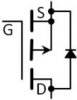
In a PMOS current flows from source to drain and body diode is directed from drain to source as shown below.

How can one decide to orient the device's diode in the direction of of normal current flow? For example, one cannot simply flip a pmos and make the current flow from drain to source. Could you please help me with this?
Note to self:
low- or high-side switch:

 www.quora.com
The page explains that for a high side driver a pmos is preferred though it requires an additional 'simple' circuitry. An nmos could also be used in a high side driver but additional circuitry required is quite complex to that for pmos. For a low side driver, an nmos is preferred.
www.quora.com
The page explains that for a high side driver a pmos is preferred though it requires an additional 'simple' circuitry. An nmos could also be used in a high side driver but additional circuitry required is quite complex to that for pmos. For a low side driver, an nmos is preferred.
In this PDF, https://www.maximintegrated.com/en/app-notes/index.mvp/id/636 , under the section "Replace Bipolar Transistors with MOSFETs", the following is said:
"Pay careful attention to a MOSFET's orientation in the circuit. MOSFETs have an intrinsic body diode that conducts current under forward-bias conditions. This current flows from the drain to the source for a PMOS FET and from the source to the drain for an NMOS FET. Whether using an NMOS or a PMOS FET as a low- or high-side switch, orient the device's body diode in the direction of normal current flow. Then, a reversed battery reverse-biases the diode and blocks the flow of current."
If one has access to the fourth terminal, i.e. body terminal, then a mosfet is a four terminal device and is a reversible device. To which terminal of the two (excluding gate terminal) one connects the body terminal determines the 'source' and 'drain' sides. This connection would constitute a body diode or internal diode of mosfet. Most, if not all, mosfets come with the connection already made.
In a PMOS current flows from source to drain and body diode is directed from drain to source as shown below.
How can one decide to orient the device's diode in the direction of of normal current flow? For example, one cannot simply flip a pmos and make the current flow from drain to source. Could you please help me with this?
Note to self:
low- or high-side switch:
What is a high-side/low-side driver in electronics?
Answer (1 of 5): What is a high-side/low-side driver in electronics? First, realize that we say “high side”, we generally mean the power supply hot or +Vcc/Vdd side of the load. And when we say “low side”, we generally mean the neutral or ground/common/return side of the load. On the left is a ...