zachtheterrible
Active Member
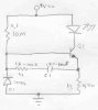
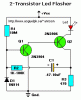
Hello. I know that this circuit that I've drawn up on the bottom here doesn't work, but I am trying to figure out why. I'm going to explain how I think that it should work, and if someone could tell me where and why my reasoning is flawed, I'd be a happy man. I also put the circuit that works on here. Here goes:
The way I see it, C1 charges up through R1 and R2, and when enough voltage is attained, Q1 opens up and C1 discharges through Q1, and while Q1 is open, the led lights up. Then the cycle starts all over again. WHERE AM I WRONG!?!?
Thankee so very much
The way I see it, C1 charges up through R1 and R2, and when enough voltage is attained, Q1 opens up and C1 discharges through Q1, and while Q1 is open, the led lights up. Then the cycle starts all over again. WHERE AM I WRONG!?!?
Thankee so very much