Electro Tech is an online community (with over 170,000 members) who enjoy talking about and building electronic circuits, projects and gadgets. To participate you need to register. Registration is free. Click here to register now.
Welcome to our site! Electro Tech is an online community (with over 170,000 members) who enjoy talking about and building electronic circuits, projects and gadgets. To participate you need to register. Registration is free. Click here to register now.
Its a matter of choice.
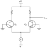
Normally, you would want to bias your BJTs/MOSFETs to have VO1 = VO2 = 0VDC.
So if you beforehand set VIN1=VIN2=0VDC, and still want to get VO1=VO2=0VDC, you will need to set:
1. RC in order to have VO1=VO2=0V.
RC = VCC / IC; (IC = IBIAS/2 since the BJTs are matched).
2. VBE in order to have the required VBE that corresponds to IB=IC/beta = IBIAS/(2*beta).
As said, you can set VB=0VDC beforehand, and set VE to the right value, according to the IB(VBE) exponential equation.
Normally, once you set IC, and VB=0Vdc, the current source IBIAS will automatically set its voltage (VE) to the required portion to give IB=IC/beta, that is if its output voltage swing is flexible enough.
By the way, i've also started learning about differential amplifiers as part of the course Linear Electronic Circuits (Also called Analog Circuits), which deals with single-stage, multi-stage, differential and feedback amplifers.
Hey alphacat,thnx for the reply.....am studyin Analog Circuits as well,which deals wth the same topics as u mentioned....But couldnt we just use coupling capacitors as we normally do in case of amplifiers????The output will be distorted in case the applied ac signal (our input) is small n fails to rise appreciably above the cut-in voltage of the B-E junction.....I guess using coupling capacitors would reduce the gain n hence the output,which is pretty small newaz,n so they arent used....
But all the circuits i hav chkd out do not show any dc bias for the B-E junction.....There is only a V_CC....No V__BB....Not even by using V_CC through a potential divider.....
But all the circuits i hav chkd out do not show any dc bias for the B-E junction.....There is only a V_CC....No V__BB....Not even by using V_CC through a potential divider.....
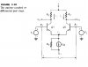
Yes they do, the first circuit feeds DC bias via R1 and R2.
You're making the mistake of assuming voltages are absolute, and they aren't, they are relative - and (like I said before) the bases are biased positive with respect to the emitters.
This site uses cookies to help personalise content, tailor your experience and to keep you logged in if you register.
By continuing to use this site, you are consenting to our use of cookies.