Here's the code I'm running
it was working fine, but I changed it to use the other button (RB5). Then instead of lighting LED6 it would light LED 1 and 3, LED 6 would flicker a bit, then after about 20 seconds it would switch, 1 and 3 would go out then 6 would go on. It still responded to button presses as expected. Switching back to RB2 the problem remained.
Does anyone have any idea what's going on? Looking at the diagram I understand why 1 and 6 are on.. if RA6 is disconnected, 1 is on and 7 is off, I would expect 1, 3 AND 6 to go off, and clearly it's something to do with those three. What am I missing?
Thanks
Code:
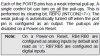
list p=18F1320
include <p18F1320.inc>
CONFIG OSC = INTIO2, WDT = OFF, LVP = OFF

org 0x000			; RESET vector
; INIT
INIT 	movlw b'01111110'
		movwf TRISA
		movlw b'00000001'
		movwf PORTA
		movlw b'11000000'
		movwf TRISB
		movlw b'11111111'
		movwf PORTB			; Set pullups

; MAIN
MAIN
		btfsc PORTB,RB2 ; Test button 2
		goto MAIN
		movlw b'10000000' ; Once it's been pressed switch the led and leave it
		movwf PORTA
		goto MAIN

END
it was working fine, but I changed it to use the other button (RB5). Then instead of lighting LED6 it would light LED 1 and 3, LED 6 would flicker a bit, then after about 20 seconds it would switch, 1 and 3 would go out then 6 would go on. It still responded to button presses as expected. Switching back to RB2 the problem remained.
Does anyone have any idea what's going on? Looking at the diagram I understand why 1 and 6 are on.. if RA6 is disconnected, 1 is on and 7 is off, I would expect 1, 3 AND 6 to go off, and clearly it's something to do with those three. What am I missing?
Thanks
")
