Continue to Site

Welcome to our site!

Electro Tech is an online community (with over 170,000 members) who enjoy talking about and building electronic circuits, projects and gadgets. To participate you need to register. Registration is free. Click here to register now.

  • Welcome to our site! Electro Tech is an online community (with over 170,000 members) who enjoy talking about and building electronic circuits, projects and gadgets. To participate you need to register. Registration is free. Click here to register now.

Bistable re-triggers if any voltage fluctuation occurs in main !

Status
Not open for further replies.
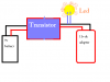
As I on the adapter.. ---
The 3hr timer is off ---
As my alarm clock begins to rang it triggers the 3hr timer and 3hr timer starts to run.. ---
Suddenly I turn off the adapter....
Now as I have said previously that led fades because the adapter contains some capacitors... ---
But in that situation when the led is fading I On the adapter again..

I repeat again...The led was not completely off.. I have turned on the adapter before the led becomes off...
Now the 3hr timer starts to run without any alarm clock signal <--This is a problem

Why is this a problem? The circuit never stopped working. The alarm told it to turn on and run for 3 hours - so it is.
 
You still have not told me if your timer circuit, and alarm circuit share a common reference point. They must have their negative supply voltages connected for any kind of signal to be reliably sent or received.

yes I have connected it reliable. with negative signal.. but I couldn't use more the one alarm clock ?

Find a way to suppress this with a start up reset timer which disables the output of the alarm until a certain amount of time has passed, or add a minimum length timer to the input of the timer circuit. A minimum length timer or a "de-bouncer" would only accept a signal that is longer than the programed time.

friend i am new in electronic field ... so how do I make this circuit... if you can give me some resource then i can build it ?

thanks in advance !
 
Sorry, been having computer trouble.

I have reworked the entire input section of the timer. Now it should not trigger when power is applied to the alarm circuit, only when the alarm is supposed to trigger it. Alarm_Vcc should be connected to the power supply of the alarm circuit, while Alarm_input is the actual signal from the alarm.

The circuit now has two start up timers, the original for the timer, and the one connected to the 555 which only starts when the alarm is first turned on. It also has the peak detector that is built into the 555 itself. This should prevent multiple triggers while the RC timer is still low.

If anything seems like it is taking too long to activate, then just make the capacitors smaller. If circuit is still giving issues then make the capacitors larger.
 

Attachments

  • timer.JPG
    timer.JPG
    111 KB · Views: 119
Thanks Dragon tamer.... I love you............................... very very very very.................. much..

:) :) :) :) :) :) :) :) :) :) :) :) :) :) :) :) :) :) :) :) :) :) :) :) :) :) :) :) :) :) :) :) :) :) :) :) :) :) :) :) :) :) :) :) :)

Friend I want to use three alarm clock to trigger this circuit according to the preset time in alarm clock !!
But In this circuit There is only One input.. so where do I connect another two alarm clock to trigger... All three alarm clock has different timing.. and they will trigger according to their time..

Thanks in advance... and for co-operation !
I love you..
May God give you happiness forever.....
 
Transistor switch help !

Hi Friends :
I have two power supply in this circuit..
1)9v dc battery.
2)11v dc adapter.

I have connected a led in 11v dc adapter for just indication..

I want to add a transistor in between the power supply... which work as switch...
I mean As I connect the 9v battery , it should turn on the transistor and it should give the 11v dc to led via adapter..

Here for good understanding I have used the word led... It is actually any load..
I just want to switch this load via transistor as I connect the 9v battery...

I have attach the image in my attachment ... please have a look !
 

Attachments

  • new.PNG
    new.PNG
    10.4 KB · Views: 124
Last edited:
The circuit users was kind enough to post is what you are after if you want to use a transistor to switch a very light load. If you want to switch a heavier load things grow. If you want to switch a load equivelent to a LED no problem but if you want to switch a larger load the transistor gets bigger and things start changing. :)

Ron
 
In the place of led .. I want to use 12v relay...
so how it will be done.......

As I connect the 9v battery the 12v relay should energize via 12volt adapter..
 
Last edited:
Relay doesnt enerize in this circuit.....???

Relay doesn't energize in this circuit..

I have attached my complete circuit diagram...

As I turn on my 12volt adapter......

I press manual switch (You can see the manual switch near 3hr timer) the 3hr timer begins to run.. untill 3hr..
So output pin 11 of bistable cd4093 stays high till 3hr and it turn the transistor becomes on and the negative supply is given to repeating timer to run...
The repeating timer is connected to relay...
As time elapsed in repeating timer the relay should energize...
Because this is 10 minutes on and 30 minutes off timer..
So as this repeating timer becomes on then with yellow led the relay should energize...

but the problem is :

The yellow led glows but the relay doesn't energize...
I have checked the voltage on relay terminals and I am getting 12v..
But I don't know why the relay doesn't run...

SO,
For just testing...
I have separated this repeating timer with 3hr timer...

I was going to run only repeating timer and I have removed the rest circuit..
So As I power on my 12v adapter...
now the relay works properly...

It energize and de-energize with repeating on/off timer..

But it doesn't work If I connect this repeating timer with 3hr timer... the yellow led in repeating timer glows but relay doesn't run..

I want ... as the 3hr timer is running it will turn on the transistor and repeating should start to run... on/off with relay...

---
Thanks in advance
 

Attachments

  • My fProject.jpg
    My fProject.jpg
    139.2 KB · Views: 105
Look at the attached. Look at the drawing users posted. Note the similarity between the two.

The transistor you select needs to be able to handle the relay coil current. For example I use a lot of Omeron MK3P5-S-12 which is a 12 volt coil 3PDT relay. The data sheet tells me the coil voltage is 12 volts and the coil resistance is 95Ω so I calculate the coil current and select my transistor based on that. The transistor base resistor is then calculated. In my circuit when the push button switch is pressed the transistor turns on and the relay energizes. When the switch is released the relay opens. Again, when using a transistor to switch a load the load needs to be defined.

Also, in my relay's case the relay current would be 12/95=126 mA so I want a transistor that can easily handle that current. I would use a 2N3904 or 2N2222 and I like the 2N2222 for switching applications. Next my 12 volt source needs to be able to source the relay coil current so I would look for at least a 12 volt 200 mA source.

Ron
 

Attachments

  • 12 volt relay.gif
    12 volt relay.gif
    5.4 KB · Views: 104
Last edited:
I have 12v and 200 ohms coil...
So what will be my requirement to switch this relay..
 
Why do you have a diode and 2.2 K resistor in parallel with the relay coil? The way the diode is in there it is backwards as to use as a flyback diode. No clue why you have the 2.2 K resistor in series with the diode but as is that diode is always on, not good! Also, as per your drawing the relay coil must not be lower than 270 ohms. No clue what your relay coil is? That is at a glance and why is there like two threads on this? I can no longer follow what you are doing.

Note the example I gave you in your other thread. Note the diode orientation.

Ron
 
Last edited:
I have 12v and 200 ohms coil...
So what will be my requirement to switch this relay..

You tell me? This is sort of a self help thing. You need to start placing some effort into learning this stuff. 12 volts / 200 Ohms = .060 amp or a 60 mA coil. So at 12 volts the transistor needs to conduct 60 mA without getting hot. I would suggest a 2N3904. The base current will be about 1/10th of the collector current so 6 mA. 12 / .006 = 2000 so try about a 1.8 K resistor. Also, per your other drawing what was the minimum R for the coil? I believe it exceeded 200 Ohms.

Ron
 
lso, per your other drawing what was the minimum R for the coil? I believe it exceeded 200 Ohms.

Friend I have 200ohms resistor coil and 12v relay
 
Why do you have a diode and 2.2 K resistor in parallel with the relay coil?
The 2.2k is series with yellow led to give led a required current & voltage !

No clue what your relay coil is?
My rely coil is 200ohms and 12v.

why is there like two threads on this? I can no longer follow what you are doing.
By mistake the another thread was posted... sorry !
 
yusuf,

Please stop opening a New Thread for every circuit component on your Project.

Moderation:E
 
You are killing me here. OK attached is what you have. Well what should be close. There is also an image with traces showing what is going on. I used a 2N2222 and the collector resistor is your relay coil of 200 Ohms. I ramp the 9 volt supply to give you a picture of exactlt what is going on. The traces are labeled. If none of this makes sense I suggest you read some transistor theory about transistors used as a switch and saturation. The traces even show the current (right side).

Did you understand what I mentioned as to your diode being backwards? This is it, this is as good as it gets.

Ron
 

Attachments

  • ltspice trans conduct.png
    ltspice trans conduct.png
    26.9 KB · Views: 108
  • Trans Conduct1.png
    Trans Conduct1.png
    13.5 KB · Views: 105
Also, the diode I questioned in series with the 2.2K or whatever resistor is not drawn as a LED but reflects being a regular diode. That tells me looking at it the Vf will be about .7 volts. There is a hell of a difference between a standard silicon diode and a LED. There is no mention of the transistor part number that is driving the relay? When the relay should be on what is the transistor base voltage?

Ron
 
Hello Reloadron ......... thank you very much.... the problem now has being solved.... as you have replied on my another thread.......
I have read all your reply ... and I have implement your circuit diagram....
And now relay is working properly !

But as the repeating timer starts the relay also starts immediately.. I want to give maximum 2 to 5 sec delay before starting the relay...

Thanks you very much again Reloadron !!!
:) :) :) :) :)
 
Status
Not open for further replies.

Latest threads

New Articles From Microcontroller Tips

Back
Top