Continue to Site

Welcome to our site!

Electro Tech is an online community (with over 170,000 members) who enjoy talking about and building electronic circuits, projects and gadgets. To participate you need to register. Registration is free. Click here to register now.

  • Welcome to our site! Electro Tech is an online community (with over 170,000 members) who enjoy talking about and building electronic circuits, projects and gadgets. To participate you need to register. Registration is free. Click here to register now.

Bistable re-triggers if any voltage fluctuation occurs in main !

Status
Not open for further replies.

yusuf

Member
Hi friends !
==============
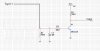
If any voltage fluctuation occurs in main supply or If the electricity goes and comes immediately this circuit triggers and the 3hr timer begins to run..

But I want it should not run until I touch the manual switch or it gets pulse from the analogue clock beeper..

And I wan to run this complete circuit with 12volt power supply because it contains 12v relay..

================
I have tested this circuit with my 7vdc adapter.. and the 3hr timer doesn't run until I manually touched the switch or it gets clock pulse.

But ...

The problem is as I power on my adapter first time ...
all circuit is off...
As I touch the manual switch the 3hr timer begins to run....
but as it runs I turn off the adapter and switched back on again immediately...
And the result is the 3hr timer & all circuit starts to run... without touching
manual switch..

I was teasing this because as I hope you all friends know that here in India there is electricity problem..
It comes and goes any time...

So I was just testing this circuit assuming that the electricity goes and comes immediately.
and the result was annoying because without touching manual switch the timer begins to run..

So I turned off the adapter...
After 5 minutes I turned on the adapter ..
but now the 3hr timer was not running and all circuit was off!!
So i touched the manual switch ...
And the 3hr timer begins to run properly !

Again I did electricity simulation by turning on and off the adapter.
And the result was same as above ...
the 3hr timer starts to run....
without touching manual switch...

So as It was running I begin to turn on and off the adapter at different times..
but as I was turning on my adapter the 3hr timer begins to run...

so I turned off the adapter...
after a few minutes I turned on..
And now all circuit was off.

And this repeats......

Friend , I though that I should be the problem of my adapter or main socket board where
I was connecting..
So I changed a new 7volt adapter and new main socket board for testing...
But now also the result was same...

Next....

Second problem...

The 3hr timer also starts if any voltage fluctuation occurs...
without touching manual switch on 3hr timer...


Third problem....

Friends , I am using 12v relay for switching on/off.
So If the 3hr timer circuit runs properly at 7volt then How should we run the 12 volt relay...
Because as I connect any power supply with is greater then 7 volt then the 3hr timer
starts to run immediately without touching manual switch...

==========

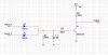
I have analyze the complete circuit deeply and the what result I got I have mentioned above :

Kindly have a look... friends

And ,
I want this all circuit should work with 12volt power supply because we have to switch on/off the pump with 12volt relay...

and also fluctuation free...
Because any fluctuation in mains run the circuit unnecessary without touching the 3hr timer manual switch..

Please have a look !

Hoping for your kind co-operation :
 

Attachments

  • Reset8.GIF
    Reset8.GIF
    15.2 KB · Views: 157
Many posts ago, IIRC, I suggested that you use a battery supply for the timer (except for the relay) and use a separate supply for the relay. I also suggested you enclose the circuit in a screened housing. Those suggestions were intended to overcome the very problems you are now encountering.
 
If you are operating the circuit at close to its minimum voltage limit, then it will be more suceptable to voltage spikes in the mains line. alec_t is right in saying that you should run the timer with a battery, this would eliminate the possiblility of any voltage spikes being introduced into the circuit. The catch is that the relay will use a decent amount of power and drain the battery much faster than it is intended to be drained so you will want a seperate supply for the relay. You can use the AC mains to drive the relay as long as the two circuits have are connected through ground.
 
OK ! Thanks Alec and Dragon tamer for you help!
I agree with your answer's . !

But I have some question's...
I hope you will clear my doubt !
Because you both are genius and great !

My question's are as follows :
1)If I use one 9v battery then for how many days it can work.. as you know this circuit will be keep on running 24hr all day !

2)This circuit is only working at 7 volt because I have tested it :

Fried my battery was low so I replaced with new 10 volt battery..
but the problem As I connect the battery the 3hr timer starts to run without
clock pluse or manual start ...
But If I use the 9v old battery which gives something 7 volt(because it is old)..

The 3hr timer doesn't starts untill I manually start or untill it gets clock pluse.. As it gets clock pluse it starts to run...

But with new one battery it starts to run as I connect the battery...

I hope this is a big problem !!

So I have tested again with my 7volt adapter and it was working with it !
But as the voltage exceeds the 3hr timer starts to run without touching manual switch !

So this was the problem with 9v battery ... as it is new one it contain 9volt... so as i connect this battery the 3hr timer begins to run...

But as I replaced with my old battery which was giving something 7v...
the circuit worked great....

SO friend how should we solve this problem !


Thanks for your co-operation uptill now !

Thanks in advance !

Yusuf
 
A 9V battery has a current rating of only 150mAh for most types, maybe 500mAh if it is a good quality battery. When you are connecting the new battery then the circuit is starting on it's own because there is no start up reset circuit in place to force the timer into a reset state after power up. You can make one with a simple RC network that will hold the reset inputs low or high until the power has stabilised.

Edit:

Replace C4 with a larger capacitor value, make it at least a 1uF cap and see if that makes a difference in your circuit.
 
Last edited:
You can make one with a simple RC network that will hold the reset inputs low or high until the power has stabilised.

Edit:

Replace C4 with a larger capacitor value, make it at least a 1uF cap and see if that makes a difference in your circuit.

Ok I have done this.... as you said ... I have increased it's value to 1uf.
and the result was :
If I connect the old battery (7v) is stay off as it deserve..

but IF I connect now 9v new battery then this circuit stays off.. but after a few second it starts again without touching manual switch !


This circuit is now working well with fluctuation free...

Thanks..
But it only works with 7volt...

As I replace 7v with new 9v battery then the circuit wait for few second then it starts to run.. without touching manual switch...
<---------- now this is a problem !
But with 7volt old battery and adapter it works fluctuation free ....
 
Last edited:
Here are a list of things to try in your circuit that may fix the problem:

1) add a pull up resistor to pin 11 of the 4060
2) remove d3 from the circuit, if d3 is important for the circuit then the pull up is a must
3) decrease R5 from 100k to 47k, this will allow more current into the input of 4093, this will make the NAND to be less sensitive to minor fluctuations in voltage
4) the amplifier on the input seems like it is not needed and could probably be bypassed, this may be amplifying any voltage fluctuations on the external circuitry that can cause a trigger to occur
 
add a pull up resistor to pin 11 of the 4060
How much value resistor should I put.. as a pull up resistor.

remove d3 from the circuit, if d3 is important for the circuit then the pull up is a must
Yes friend D3 is important so where do I put the pull up resistor and what will be the value of pull up resistor.

the amplifier on the input seems like it is not needed and could probably be bypassed, this may be amplifying any voltage fluctuations on the external circuitry that can cause a trigger to occur

This is analogue clock amplifier where an simple analogue alarm clock beeper is connected ... so that it can trigger this 3hr timer circuit at the time which is set by analogue alarm clock..

This is working great with 7volt.. First I set the time in the analogue alarm clock.. and this clock beeps at the preset time in turn the 3hr timer is activated.... and Here you can a manual switch is for just testing the circuit without analogue alarm clock..

============
Friend please if possible can you explain why this circuit work properly with 7v and not with 8v or 9v etc...
 
Your amplifier circuit does not need to be there if it just connected to an alarm clock. Simply replace the amplifier with a sing 2N2222 transistor with a 10k resistor on the collector, and a 10k resistor on the base that connects to the alarm clock. Each alarm clock input will need its own diode so that they do not short each other out, they can both use the same 10k resistor. The emitter of the transistor should connect directly to ground. The input for the trigger will connect to the collector of the transistor, and this will be the output of the circuit. You must make sure that both circuits have a ground in common otherwise they can cause false signals or even damage each other. For the pull up resistor on pin 11, make it a 10k. I would also make C4 much larger so that the circuit the timer circuit has time to stabilize, and the alarm clock also has time to stabilize. Make C4 a 10uF to 100uF cap, this should give a large enough time constant for each circuit to stabilize.

Edit:

Add a 1uF capacitor to the diodes that are from the alarm clock, connect this cap between the diode and ground. You will also need another cap in parallel with the cap to discharge it at a fairly slow rate. Make the resistor a 47k. Both of these will create a peak detector so that high frequency inputs from the alarm clock will be ignored, and only large overall inputs will trigger the circuit. If it seems like the peak detector is not doing a good enough job, increase the value of the resistor or the cap to create a larger time constant.
 
Last edited:
Thanks dragon very much...
I will try as you said....
But as I am new in electronic I can make too mistakes without circuit diagram...
So can give me a modified circuit diagram so that I can make easily !!

and again
Please if possible can you explain why this circuit work properly with 7v and not with 8v or 9v etc...
 
Here is the schematic of what your new input should look like. You still have to connect the alarm clock to the timer schematic through their ground. Other wise they are both different circuits and will not work properly.

Your circuit is not working properly because when power is applied, the circuit has to stabilize before any activity can start. When the battery is first applied, there is a lot of noise in the circuit that the circuit needs to ignore before all of the voltages settle at their proper levels. That is why I stated that you should increase the value of C4, it will increase the amount of time that the circuit ignores the noise before it starts working.

The alarm clock itself may be the cause of the problem, if it runs off of the mains frequency for timing, then it is possible that there is on voltage regulator inside the circuit. If that is the case then your timer is detecting the voltage ripple that is in the alarm clock and is mistaking it as an input signal. That could explain why the circuit works at 9V and not 7V.
 

Attachments

  • untitled.JPG
    untitled.JPG
    93.4 KB · Views: 128
You might try a 390k across c4. Otherwise you may need a better power on reset circuit to assure the latch is reset on power on.
 
Also the clock circuit is very noise sensitive and could be picking up noise from the plugging and unplugging of the supply. What are the voltage levels on the clock signals. You might be better of filtering those on the input and creating the pulse inside your circuit.
 
there is no start up reset circuit in place to force the timer into a reset state after power up
I disagree. I designed-in the power-on reset circuit consisting of D1, R7, C4. Increase C4 as Dragon Tamer suggests, if you wish; it will hold the reset state for longer.
can you explain why this circuit work properly with 7v and not with 8v or 9v etc..
Yes. The circuit was designed to use a 6V supply, not a PP3 9V supply (a PP3 battery wouldn't last long). I advised you in previous posts that you must adjust R3 so that the collector of Q1 is at about 2/3 of the supply voltage, i.e. about 4V for a 6V supply (6V for a 9V supply). If you use >6V (why would you want to?) you must adjust R3 and also may have to reduce the value of R4. Simulation shows that R4=22k would be ok for a 9V supply.

To reduce current consumption, make R8 = 220k and connect another npn transistor to Q2 to make a Darlington-configuration driver for the relay. Also, remove LEDs LED1 and LED2 (which are only there to check circuit operation during set-up). The circuit consumption will then be about 100 microamps and a set of 4 AA cells should power it for at least 10,000 hrs. If you find you can do without the beeper pulse amplifier then battery life would be even longer.
 
Post deleted
 
Last edited:
Thanks "dragon tamer" very much for your great help !

But with adding diode at the output of clock.. The clock circuit can't trigger the 3hr timer...

But it is working properly by removing the diode and connecting directly as shown in my circuit diagram which I have attached.. !

But I want to use three analogue clock so ....
Here there will be three input...

So how should..... I accomplish this task...

I have following diode in my workshop :
IN4148
IN4007

===============


Friend one more help !

Now this circuit work from 9v and more then 9v also properly...

And by increasing the size of c4 it has done the work...

But I need one more help...

As I turn on my adapter the circuit stays off...
As My clock alarm starts , it triggers the 3hr timer...

But as I turn off the adapter...
The led's on 3hr timer fades slowly and then off... because there is a adapter which is containing some capacitor so after turning off the adapter the capacitor contains some voltages.. so the led gets the supply until the capacitor discharge !


And again after the led becomes off..
I again on the adapter and the timer doesn't starts to run...

This is also good... As I deserve..

Because the problem of fluctuation solves here...
-----------
But one problem remains....

As I on the adapter.. ---
The 3hr timer is off ---
As my alarm clock begins to rang it triggers the 3hr timer and 3hr timer starts to run.. ---
Suddenly I turn off the adapter....
Now as I have said previously that led fades because the adapter contains some capacitors... ---
But in that situation when the led is fading I On the adapter again..

I repeat again...The led was not completely off.. I have turned on the adapter before the led becomes off...
Now the 3hr timer starts to run without any alarm clock signal <--This is a problem

This circuit works fluctuation free after the 3hr led becomes of or the adapter discharges completely..
So after the adapter is discharged the led is also turned off..
so again turning on/off the adapter doesn't turn on the 3hr timer until the alarm clock signal is available...

So friend this was the problem...

Thanks again for co-operation ...
:)
 

Attachments

  • new.JPG
    new.JPG
    93.5 KB · Views: 128
Last edited:
The problem is still there because you are not using a battery to power the timer.
 
Ya friend.... But I hope It can be solved....
I will surely use battery to power!!

But I also hope we all can solved this problem ..... then we can learn new things...

SO I have posted...
Dont be angry alec... just we have to use our little mind..

And I hope we will learn new thing....

I can use battery.....
But I am also posting long long post with images.. so that every one can learn from my problem !!
:)
 
Last edited:
And I hope we will learn new thing..
I hope so too. I'm interested to see how Dragon Tamer's approach pans out.
 
I hope so too. I'm interested to see how Dragon Tamer's approach pans out.

I'm sensing a smart remark buried in that post, regardless I'm going to let it slide.

yusuf,
You still have not told me if your timer circuit, and alarm circuit share a common reference point. They must have their negative supply voltages connected for any kind of signal to be reliably sent or received.

Secondly, your circuit is most likely resetting after you apply power to the alarm circuit because there is a voltage spike on the alarm output during start up. Find a way to suppress this with a start up reset timer which disables the output of the alarm until a certain amount of time has passed, or add a minimum length timer to the input of the timer circuit. A minimum length timer or a "de-bouncer" would only accept a signal that is longer than the programed time. The peak detector that I posted will not suppress the start up spikes, it will actually detect them as a valid input and trigger the timer.

The easiest way to ensure that there is no false triggering is to have both the alarm and the timer receive power at the same time. I am wondering why you are going through all this trouble to test them if they are intended to stay on all the time in first place. If they both receive power at the same time then the timer's start up reset would force it to ignore any start up spikes from the input of the alarm while it is starting up.
 
Status
Not open for further replies.

Latest threads

New Articles From Microcontroller Tips

Back
Top