Continue to Site

Welcome to our site!

Electro Tech is an online community (with over 170,000 members) who enjoy talking about and building electronic circuits, projects and gadgets. To participate you need to register. Registration is free. Click here to register now.

  • Welcome to our site! Electro Tech is an online community (with over 170,000 members) who enjoy talking about and building electronic circuits, projects and gadgets. To participate you need to register. Registration is free. Click here to register now.

Bipolar stepper driver with 4000 line chips and mosfets

Status
Not open for further replies.

crazybuoy

Member
In these two circuits for bipolar stepper, they dont have any thing to adjust. I dont want to involve in a critical situation like adjusting Vref volt in L297 & L298 driver. I have blown up 3 L297 due to Vref volt problem.

These two circuits will also provide higher range of volt and amp.

I want to drive my stepper motor (bigger one = 4kg) at 35-40v.

Please tell me if there any drawback in following drivers as compared to L297 & L298 driver or in general.

Thanks
du9CL.gif

bipolar_stepperP2.gif
 
I want to drive my stepper motor (bigger one = 4kg) at 35-40v.
At low voltage (<20V) you can tie the gates of the P &N MOSFETS together. At high voltage you need a different way to drive the top MOSFET. Remember that the Gate-Source voltage should never be more than 20 volts. Some parts have a lower spec.

What is the purpose of "enable". Do you want the motors to free run or to lock up?
 
I want to use H_Bridge made of mosfets because it provides higher range of volt & amp. I want to use 35-40 volt to increase motor speed only.

So plz suggest me how to make any change in circuit to make it work at higher volt. Or you can suggest another circuit.
 
You need a "high side gate driver" for the top two MOSFETs.
There are several types of ICs that do that. Usually they drive N type MOSFETs because they are better parts.

There are some simple drivers (not using IC) that work with P type.
I don't have time now, but some one will help you with this.
 
POST ISSUE: 8 of 2016_11_02

HI CB,

You don't post too often on ETO.:)

Where are you at? If you put it next to 'Location' on your user page it will show in the box at the left of your posts. It helps us when answering questions to know where members are.

I haven't analyzed the logic or functional design of the two circuits you posted, but I have done a parametric analysis and I am afraid to say that:
(1) The MOSFETs (ZVN4206A/ZVP4105A) in the circuit #1 (lower left) are not man enough for the job and will probably blow.
(2) The NOSFETs (IRLML2803/IRLML6302) in circuit #2 are even less adequate and will blow instantly with the size of stepper motor you imply.
(3) Driving MOSFET gates with CD4000 series logic is OK for low speed switching, but for higher speeds it is inadequate, due to the huge effective input capacitance of MOSFETS, especially as you are driving two MOSFET gates with one CMOS drive signal.
(4) There are no gate drive stopping/shaping resistors.
(5) You plan to use 30V to 35V supply rails, but the IRLML6303 NMOSFET only has a VDSmax of 20V. A 60V and above, NMOSFET would be advisable
(6) You plant to use 30V to 35V supply rails, but the IRLML2803 PMOSFET only has a VDSmax of 30V. A 60V, and above PMOSFET would be advisable
Note that, for various reasons, you cannot use a 30V VDXmax MOSFET on a 30V supply line, for example. Similarly, you could not use a 1A IDmax MOSFET to switch a 1A load, for example. You must keep within the bounds of the MOSFET's safe operating area (SOA). If the MOSFETs data sheet does not mention SOA, you have to take a guess, or preferably chose a properly specified device.
(7) The IRLML2803PbF data sheet does not include a maximum VGSth value, which means that it is impossible to design this device into a circuit.

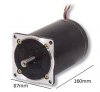
You ask about the L297 and L298: they are both widely used bridge chips and are well behaved, but you must keep within the maximum ratings listed on the data sheets. The L297 is only suitable for relatively light loads, but the L298 is much more manly. Making your own bridge will give you more flexibility and potential voltage/power capability and, for your intended application, is the best way to go, I would think.

I just had a quick look at the functional design and would advise that it would be far better to eliminate the two enable NMOSFETs and do the enable function by logic. That would mean driving each of the four MOSFET gates, in each of the two H bridges, separately (which would be a good move anyway).

spec

DATASHEETS
ZVN4206A: http://www.diodes.com/_files/datasheets/ZVN4206A.pdf
ZVP4105A:
https://www.diodes.com/_files/datasheets/ZVP4105A.pdf

IRLML6302PbF: https://www.infineon.com/dgdl/irlml6302pbf.pdf?fileId=5546d462533600a4015356688c702627
IRLML2803PbF: https://www.infineon.com/dgdl/irlml2803pbf.pdf?fileId=5546d462533600a4015356682aff260f
L297: https://www.st.com/content/ccc/reso...df/jcr:content/translations/en.CD00000063.pdf
L298: https://www.st.com/content/ccc/reso...df/jcr:content/translations/en.CD00000240.pdf
 
Last edited:
Here is a high side P-MOSFET driver method I have used many times.
The drive signal is 0 and 12 volts (with "Logic Level" MOSFETs you can use 0 to 5v)
When the signal jumps to 12V, D1 keeps the gate at 0.7 volts above the supply. (off)
When the signal jumps to 0V, the date will be 11.3 volts below supply. (on)
If no signal happens for a long time the Gate-Source voltage will go to zero.
I usually have the RC time constant at 10 to 100x the switching time. T=R1 X C1.
upload_2016-11-1_17-30-45.png

I have used this many time with a supply of 100 to 400 volts.
 
https://www.onsemi.com/pub_link/Collateral/NCP5106-D.PDF
This little 8 pin IC will take TTL level signals and drive two N-MOSFETs in a half bridge. It is built for 400 volt supplies but will work at your 35 volts fine. Note it used N fets.
NCP5106B. I think you need the "B".
upload_2016-11-1_19-48-56.png

----edited----
The circuits in posts #6 & 7 can not be run for a long time at 0% or 100%. They require a signal all the time. 10% through 90%. If set to 100% or 0% the top driver will fail in the foo direction.
 
Hi Ron,

You can get boost gate drivers that work from 'DC'. They have self-oscillating capacitor-boost supplies. But these days, with decent PMOSFETs being available, mostly, you do not need to boost the MOSFET drive voltage. Also, I always feel that, in general, it is preferable to keep the drain/gate away from the fire and brimstone of the load if possible.

spec
 
Hi, Spec,

The mosfets shown in circuits are not a problem, they can be changed later. My cnc hardware spec are:
200 steps per motor rev, v-shape lead screw with 1.5mm pitch, so 133 steps/mm, I need about 5000mm/minute speed using Mach3.

I think this 40xx chips may not be able to maintain above high speed switching.

Am i right?
 
Last edited:
Hi CB,

The mosfets shown in circuits are not a problem, they can be changed later.
That is good, but bear in mind that the replacement MOSFETs will be much more substantial and will be in TO220, or similar size, packages and will need to be mounted on heatsinks. Also the MOSFETS will be much more, expensive, probably, $4.00US.
My cnc hardware spec are: 200 steps per motor rev, v-shape lead screw with 1.5mm pitch, so 133 steps/mm, I need about 5000mm/minute speed using Mach3. I think this 40xx chips may not be able to maintain above high speed switching. Am i right?
From what you say: stepper motor changes per second (CPS) = (5,000*133)/(200 *60) = 55.42 CPS

From the above calculation, the stepper motor changes per second are not particularly fast. But, even so, if the MOSFET gates are not driven fast, the MOSFETs will overheat so, as you say, a CD4000 series output would not be adequate. Because the replacement MOSFETs will have relatively large chips inside the package, they will also have correspondingly huge input capacitances (around 10nF), which will require quite a lot of current drive to switch fast.

We really need full details of your proposed stepper motor to advise on designing a reliable and efficient stepper motor drive circuit for your CNC system. So could you please post as much information as possible on the stepper motor? A manufacture's part number would help but, ideally, a link to a data sheet for the motor.

Just one final word, this is no simple task. Driving a powerful stepper motor requires a thorough design and good layout. Decoupling will be important too, and a solid DC supply line will be essential.:)

spec
 
Last edited:
It is just my idea if 4027 & 4030 can handle 55.42 CPS switching speed or not. Do you think that it really can handle the above switching speed?
I have enough number of IRFZ44n (n-channel) and I only need to buy its equivalent p-channel IRF5305 to build full h-bridge.

But, even so, if the MOSFET gates are not driven fast, the MOSFETs will overheat

So should I increase switching speed i.e. 7-8000mm/minute?

My bipolar stepper motor has 3 ohm winding resistance. Unfortunately, it has not any label on motor body. My stepper motor is same as attached with an attached motor image. It includes motor measurement and its weight is 4kg.
 

Attachments

  • My stepper motor.jpg
    My stepper motor.jpg
    15.6 KB · Views: 302
It is the original image of my bipolar stepper motor. The fifth (middle) pin is for ground.
 

Attachments

  • My stepper motor 1.jpg
    My stepper motor 1.jpg
    115.3 KB · Views: 302
It is just my idea if 4027 & 4030 can handle 55.42 CPS switching speed or not. Do you think that it really can handle the above switching speed?
There is two as aspects to switching speed:
(1) The frequency (55.42 Hz)
(2) The rise and fall times of the switching waveform.
The CD4027 and CD4030 logic chips will handle the 55.42 Hz switching frequency no trouble whatsoever. They will also provide fast rise and fall times if they were switching a light load, like the input of another CDxxxx chip. But they would be woefully slow switching the gate of a big MOSFET.

Your best bet is to realise the logic with 74HCxxxx/ 74AHCxxxx logic chips. Then you would need a driver chip between the output from the logic circuit and the MOSFET gates. We can design a circuit to do this.

I have enough number of IRFZ44n (n-channel) and I only need to buy its equivalent p-channel IRF5305 to build full h-bridge.
The ZRFZ44n NMOSFET should just do the job. The IRF5305 is more marginal with its 60 mili Ohm on resistance, so it would be wise to hold off buying those.

So should I increase switching speed i.e. 7-8000mm/minute?
No, the lower the switching frequency the better as far as the MOSFETs are concerned.

My bipolar stepper motor has 3 ohm winding resistance. Unfortunately, it has not any label on motor body. My stepper motor is same as attached with an attached motor image. It includes motor measurement and its weight is 4kg.
That represents quite a load at 30V (30V/3 Ohms = 10A). As I said not a trivial design, but doable.:)

spec

DATASHEETS
https://www.infineon.com/dgdl/irfz44n.pdf?fileId=5546d462533600a40153563b3575220b
https://www.infineon.com/dgdl/irf5305pbf.pdf?fileId=5546d462533600a4015355e370101993
 
The ZRFZ44n NMOSFET should just do the job. The IRF5305 is more marginal with its 60 mili Ohm on resistance, so it would be wise to hold off buying those.

I think IRF4905 PMosfet is another equivalent one for IRFZ44n NMosfet. Is it?
If not, then which PMosfet is equivalent for IRFZ44n?

If there is not any equivalent PMosfet suitablly for IRFZ44n, then which N&P Mosfet (more than 50V & 30A) combination is suitable for full h-bridge?
 
Last edited:
I think IRF4905 PMosfet is another equivalent one for IRFZ44n NMosfet. Is it?
If not, then which PMosfet is equivalent for IRFZ44n?

If there is not any equivalent PMosfet suitablly for IRFZ44n, then which N&P Mosfet (more than 50V & 30A) combination is suitable for full h-bridge?

There is no such thing as a complementary pair of transistors of any type, BJT or MOSFET, any more than there is a complimentary man and woman- they are different animals.:D

I will find a more suitable N&P MOSFET for your application.

spec
 
It is the original image of my bipolar stepper motor. The fifth (middle) pin is for ground

I think your wrong about the "fifth pin" being ground. A 5 pin/wire stepper usually has the fifth pin as the supply not ground. The other four pins are grounded in a sequence to make the step movements.

Also by using only full steps of the motor, you are limited in precision of table movement to the pitch of your lead screw. Most CNC's use smaller steps from a driver chip to get more resolution in the table movements. Most driver chips allow 1/2, 1/4 and even micro steps to be made.
 
Last edited:
The time and money that will be spent building and trouble shooting a DIY driver board will be, in the end higher than just buying the correct ready made circuit.

Yes, you are right. I also want the same. But I just want to specify which parts are well matched to my application.

That represents quite a load at 30V (30V/3 Ohms = 10A).

If I increase the volt i.e. 40v (40v/3 ohm = 13.3A), that is why I want to use NP-Mosfet H-bridge. I think that without increasing the volt at most 40V, I may not be able to achieve 7000mm/minute motor speed. And I think, any Bridge driver may not handle this higher Amp.

I think your wrong about the "fifth pin" being ground. A 5 pin/wire stepper usually has the fifth pin as the supply not ground. The other four pins are grounded in a sequence to make the step movements.

I have checked the connections by opening motor's back cover, the fifth pin/wire is connected to motor body and other four are coil connections.
 
Status
Not open for further replies.

Latest threads

New Articles From Microcontroller Tips

Back
Top