Continue to Site

Welcome to our site!

Electro Tech is an online community (with over 170,000 members) who enjoy talking about and building electronic circuits, projects and gadgets. To participate you need to register. Registration is free. Click here to register now.

  • Welcome to our site! Electro Tech is an online community (with over 170,000 members) who enjoy talking about and building electronic circuits, projects and gadgets. To participate you need to register. Registration is free. Click here to register now.

Bipolar ADC using precision rectifier

Status
Not open for further replies.

Hero999

Banned
I've just had an idea, forgive me if this is old news but rather than biasing at ½Vref use a precision rectifier and comparator.

The comparator will provide a high/low signal indicating whether it's + or -.

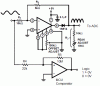
The precision rectifier shown here (for which I take no credit, I found the circuit on the datasheet for an op-amp) has the advantage of only needing a single supply, although it has a loss of 2.

Using a precision rectifier has the advantage of effectively doubling the precision of the ADC.

If hysteresis is added to the comparator, it should be < the V/bit of the ADC. In this example 22k/10M×5 = 11mV so for a 8-bit DAC is fine 5/256 = 19.53mV.
 

Attachments

  • AC ADC.GIF
    AC ADC.GIF
    14.1 KB · Views: 522
Last edited:
Shouldn't the hysteresis loop go to the non-inverting input of the comparator? Good idea if you can sync the sample cap of the ADC with the reading of the sign from the comparator reliably.
 
Last edited:
Yes, you're right, I had is configured as a linear inverting amplifier. It would have never worked, just oscillated.

I've fixed it.

By the way, I got the schematic from the CA3140 datasheet. I had the schematic on my hard drive and had removed the par number for some silly reason.

https://www.electro-tech-online.com/custompdfs/2009/08/fn957.pdf
 
Yes, you're right, I had is configured as a linear inverting amplifier. It would have never worked, just oscillated.

I've fixed it.

By the way, I got the schematic from the CA3140 datasheet. I had the schematic on my hard drive and had removed the par number for some silly reason.

https://www.electro-tech-online.com/custompdfs/2009/08/fn957-1.pdf

Hi,
I have used that prec rectifier from the CA3140, it works OK.

Your polarity detector will only work correctly if the sinewave is centred about zero volts.
It detects the offset from zero, so if the offset is negative it will sign negative, but will go sign positive on every positive half wave of the sinewave.???
 
It's DC coupled to yes, that will happen.

AC coupling via a suitable capacitor will "fix" this but I don't see the problem if this is going to be used in something like a DC meter.
 
Status
Not open for further replies.

New Articles From Microcontroller Tips

Back
Top