We've received our pilot boards from the manufacturer factory and we have a major problem.
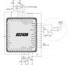
We have on board two crystal that are connected to the MCU - 32MHz and 32.768KHz.
Both of the crystal show unsteady frequency at their outputs.
I'd like to ask you please 2 questions:
1. If you had experience with these phenomenon, Could you please write here the reasons that it occured and how did you solve it?
What have you experienced that caused the crystal to output unsteady frequency?
2. How can i know what is the voltage that should be input to the Crystals?
It isnt mentioned in datasheet:
http://www.abracon.com/Resonators/abs25.pdf (32.768KHz)
**broken link removed** (32MHz)
Should both pins of each Crystal receive same input voltage?
Thank you very much for any help.

")
")
