Continue to Site

Welcome to our site!

Electro Tech is an online community (with over 170,000 members) who enjoy talking about and building electronic circuits, projects and gadgets. To participate you need to register. Registration is free. Click here to register now.

  • Welcome to our site! Electro Tech is an online community (with over 170,000 members) who enjoy talking about and building electronic circuits, projects and gadgets. To participate you need to register. Registration is free. Click here to register now.

Bicycle POV

Status
Not open for further replies.
andrew12345678 said:
I have ordered 3 16F88 so i will be definately using a PIC.

I guess i'll have to test the magnets and if they arent strong enough i can mount them closer. Good thing you reminded me about the inverse square law, i'll need that for end of year exams :D

Microchip is actually very good at handing out free samples of their chips. You'll need a non-yahoo/hotmail/etc. email account, though:

http://sample.microchip.com/Default.aspx?testCookies=true

Also, I've found that reed switches work well (perhaps even better), and they in general cost less than an Hall effect sensors.

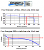
As for LED brightness, I would get the brightest you can find. Then you can run them at lower currents to save on battery power.

Figure out a way to mount the batteries as close to the wheel center as possible. I rode 40 mi. with a bicycle pov on my back wheel, and I definitely had to work harder to pedal it. I also didn't distribute the batteries evenly around the wheel, so there was an imbalance which was very noticeable at higher speeds.

Finally, consider using AAA's instead of AA's. They are 1/2 the weight but still have 1200 mAH which probably will be enough to power you through the entire race - it all depends on your LEDs.
 
well, i hadnt decided on the batteries, i was leaning toward AAA rechargeable Ni-MH, but I dont know that rechargeables have enough mAH in them, so throw-aways are more likely. another option I may have is to use 1 of those 12V batteries and pull the shell off to get the cells inside.

as for the LED's i dont think i will use the brightest, cause they are expensive, then again I could order those ones off ebay... they didnt seem too bad.

what kind of viewing angle do i need, is it the higher the better or the lower the better? im guessing higher.

I'll have to have more of a look thisafter noon cause i have school now, I'll also make sure I ask my teacher about a programmer, although i doubt he or the school will have one.
 
You might ask around to see of there is a robotics club in your area - they could be very helpful for a project like this.
 
Instead of a Hall Effect sensor, it might be easier on your schedule to synchronize to the wheel with something simple like a leaf switch. It should offer a very small drag.

Are these solid wheels or spoked?

If you choose AVR you can build a programmer for almost free. And you can use a trial version of BASIC. It only supports programming half of the memory (for free) which hopefully is enough.
 
Last edited:
I dont think there is any robotics clubs nearby, but i dont know if they would be much help.

Will a Hall Effect Sensor require extra electronics to interface it with a PIC?
A reede switch may be the way to go, but from what I hear they are too slow for a spoke project as wheels can turn too quickly.

The wheels are spoked and on 1 side (the external side) we put hubcaps made of corflute, which is like 3-ply cardboard except its made of plastic, and is easy enough to put holes in to poke LED's through.

Yeah, i know about the AVR programmer, but i could find a version of Basic I could use for it and i asked in the Microcontroller forum, but no one seemed to know there. Although it hasnt quite been 24 hours, but oh well...

Oh, and I may be able to build a programmer for my final electronics project, which we are starting next week (whilst finishing our current one)

Thought about rain proofing, will probably put the main circuit in a zip-lock bag and some hotglue waterproofing on LED legs.

Still need to find some LED's, the problem with ebay is the shipping cost of $10 :(
 
Last edited:
Ok, I have compiled a small list of links to LEDs that I think would be suitable, what do you guys think?

These are 3 packs:
http://www.dse.com.au/cgi-bin/dse.storefront/46b2cfd00a4806b82740c0a87f9c071e/Product/View/Z3891
http://www.dse.com.au/cgi-bin/dse.storefront/46b2cfd00a4806b82740c0a87f9c071e/Product/View/Z3892

Singles:
http://www.dse.com.au/cgi-bin/dse.storefront/46b2cfd00a4806b82740c0a87f9c071e/Product/View/Z4034
http://www.dse.com.au/cgi-bin/dse.storefront/46b2cfd00a4806b82740c0a87f9c071e/Product/View/Z4033
http://www.dse.com.au/cgi-bin/dse.storefront/46b2cfd00a4806b82740c0a87f9c071e/Product/View/Z4035


Oh, and at the prices im finding, we will probably stick to an 8 LED display.

You are more likely to know what will and wont work, so after looking at thiose, do you think they will be any good?
 
maybe Futurlec, an Australian company, delivers to AU faster than they deliver to the US ... lots of cheap led there. www.futurlec.com

Don't worry about rain proofing. at the voltages you're using, you'll need salt water to conduct any voltage, and likely it'll just cause some corrosion. once you get it assembled and tested, paint the circuit board solder joints with some sort of anti-rust paint and you're done.

a hall switch or a reed switch both require one line from the pic. the hall switch needs to be pulled up/down, powered and grounded. a reed switch needs to be pulled up/down and grounded. so one less connection for the reed switch vs the hall. If you use one of the pins with an internal pull-up on your pic, then you're down to only needed two connections for a reed switch, signal and ground.

problem with a reed switch is response time and longevity. Most switches are only rated for a few thousand contact closures, and in the course of their normal life, this would be years and years. but spinning on a hub at 60+ RPM, you quickly accumulate thousands of contact closures. if this is a one time use project, it won't make much difference, if you want it to last, go solid state. Another thing about reed switches - they're spindly pieces of metal inside a glass tube, sounds kinda fragile to me, compared to the hall sensor which is just some silicon sealed in a block of epoxy.
 
justDIY said:
maybe Futurlec, an Australian company, delivers to AU faster than they deliver to the US ... lots of cheap led there. www.futurlec.com

Don't worry about rain proofing. at the voltages you're using, you'll need salt water to conduct any voltage, and likely it'll just cause some corrosion. once you get it assembled and tested, paint the circuit board solder joints with some sort of anti-rust paint and you're done.

a hall switch or a reed switch both require one line from the pic. the hall switch needs to be pulled up/down, powered and grounded. a reed switch needs to be pulled up/down and grounded. so one less connection for the reed switch vs the hall. If you use one of the pins with an internal pull-up on your pic, then you're down to only needed two connections for a reed switch, signal and ground.

problem with a reed switch is response time and longevity. Most switches are only rated for a few thousand contact closures, and in the course of their normal life, this would be years and years. but spinning on a hub at 60+ RPM, you quickly accumulate thousands of contact closures. if this is a one time use project, it won't make much difference, if you want it to last, go solid state. Another thing about reed switches - they're spindly pieces of metal inside a glass tube, sounds kinda fragile to me, compared to the hall sensor which is just some silicon sealed in a block of epoxy.

ok, im happy to use a Hall effect sensor, its less fragile, will last longer and seems easy enough to use, i was worried i would need an amplifier of some type, but now i dont think i will.

well, this is more then 1 time use, once a year for 24 hours for as many years as it lasts/is still wanted/still fits in the rules.

now, i just want to double check with you on these LED ratings
i dont think this one will be any good, the Forward Voltage is too high, correct?

Blue Super bright from futurlec
Symbol----Parameter----------Conditions ----------Typ----Max ---Units
Vf--------Forward Voltage----Vcc=Min,Ii=-12mA-------3.5----4.0 -----V

But the Orange or Yellow should be OK?
Symbol----Parameter----------Conditions ----------Typ----Max ---Units
Vf--------Forward Voltage----Vcc=Min,Ii=-12mA--------2.1----2.5-----V


Thankyou so much for all your help, once i have confirmed the colour with my teammates ill be ready to start building.
 
andrew12345678 said:
ok, im happy to use a Hall effect sensor, its less fragile, will last longer and seems easy enough to use, i was worried i would need an amplifier of some type, but now i dont think i will.

A digital output Hall-effect sensor will have a built-in-amplifier. There are linear output versions, but you'll want to use a digital one.

andrew12345678 said:
well, this is more then 1 time use, once a year for 24 hours for as many years as it lasts/is still wanted/still fits in the rules.

now, i just want to double check with you on these LED ratings
i dont think this one will be any good, the Forward Voltage is too high, correct?

This is the interesting part of the engineering... you have to decide:

- what voltage to run your PIC and any other support chips at
- what voltage to supply to your LEDs
- how to provide that voltage (some number of 1.5 volt alkalines or some number of 1.2 volt NiMH cells or maybe a 3.7 volt Li-ion battery)

For instance, if your PIC can run at 3 volts, you can get away with two 1.5 volt alkaline batteries and you can drive red, yellow or orange LEDs (but not blue or white). Also check the voltage requirement for the Hall-effect sensor to ensure that it can run at 3 volts - some require 5.
 
those ratings are excessive for the leds ... red/yellow is going to be 1.8 to 2.0 volts, I'd consider 2.2v to be "high". for blue/green many of them are rated 3.5v but I find 3.0 to 3.3v to work excellent. 4.0v is definitely excessive

pc88 brings up a good point, and that is to be careful in your selection of hall effect sensors. I've found there to be at least three types:

linear: outputs an analog voltage or current in relation to field strength

latching aka unipolar: works like a toggle switch, North field polarity turns it on, South field polarity turns it off

non-latching aka omnipolar: works like a momentary switch, on when field is present, off the rest of the time.

you want the non-latching variety, since you just want a quick HI-lo each time the magnet passes the sensor.
 
The viewing angle of the LEDs on the vehicle will be wide (especially when it is sliding on its side!). Then you need wide-angle LEDs. Most very bright LEDs have a focussed very narrow angle and can't be seen if you are not exactly in the beam.

A 3V alkaline battery with a load drops to about 2.4V very quickly. Then the voltage drops slower to 2.0v when it can be considered dead. Use more cells.
 
"1.5V" alkalines are only 1.5V for the first 5-10% of their life. It's the worst of both worlds - You have to cope with 1.5V when new, and then you have to deal with 1.2V to 1.0 which is what alkalines provide for most of their remaining life. Example: 3 cells start at 4.5V and fall quickly to 3.6V and eventually to 3.0V.

I use NiMH almost exclusively now because they have a much flatter voltage output.
 
Energizer's lithium throw away battery cells hold their voltage up much better than alkaline cells:
 

Attachments

  • AAA comparison.PNG
    AAA comparison.PNG
    45.4 KB · Views: 184
Re Hall-effect sensors... there's another thing to look look out for. There are "continuous-time" sensors and "micro-power" sensors. The "micro-power" type save power by having a very small duty cycle (about .1 %), and they will only be awake around 20 times a second. A continuous-time sensor is on all the time and will give you much better resolution and better image coherence from one revolution to the next.
 
Oh boy, lots of complications :(

Ok, hmm...

I think I will start with the Hall Effect sensor. The one I thought I was going to use turned out to be
Linear :( and requires min 4.5V. Data sheet: https://www.ortodoxism.ro/datasheets/allegromicrosystems/3503.pdf

It seems to be the only one that is readily available, but if I use ADC on the PIC would I be able to use it still? or would that over complicate things?

Even if I could use it that means I need a minimum voltage off 4.5V, so I will need 4 1.5V cells, 6V, as 3 batteries wont last long enough and 4.5V is the minimum voltage for the Hall Effect Sensor. The Hall effect sensor has a maximum rating of 6 V, so no resistor is required for it.

Now according to my calculations (which I don’t trust for a second) I need a resistor of 25 Ohms on the PSU of the PIC, because it has a maximum rating of 5V and 25 Ohms will provide the necessary voltage drop.

Then, going with either the yellow or orange LED, @2V I will need a 350 Ohm Resister per LED.

Correct?

I know the Pinouts arent strictly correct, but have I got the general idea?
 

Attachments

  • LEDPov1.JPG
    LEDPov1.JPG
    25.2 KB · Views: 178
Instead of the 3503, check out the 3213:

**broken link removed**

Even though it's described as being "micro-power", it has a duty cycle of 25% and is awake 3,000-4,000 times a second which is plenty resolution for your POV. Also, it has a minimum supply voltage of 2.4V which makes it very nice for battery powered applications.

Also, don't use a resistor to regulate the voltage to the PIC - your supply voltage will vary wildly as the PIC varies the amount of current it uses. Just try to work things out so you can run everything straight from the batteries.
 
Last edited:
@justDIY: Thanks for that site, I had to go out before I could look up the contact info, but I did manage to find the site.

@pc88: Thanks for that link, you managed to find it before i even had a chance to look, made my job easier :)

will have to do something about it tomorrow, its too late at night for me to concentrate on anything
 
Status
Not open for further replies.

Latest threads

New Articles From Microcontroller Tips

Back
Top