Continue to Site

Welcome to our site!

Electro Tech is an online community (with over 170,000 members) who enjoy talking about and building electronic circuits, projects and gadgets. To participate you need to register. Registration is free. Click here to register now.

  • Welcome to our site! Electro Tech is an online community (with over 170,000 members) who enjoy talking about and building electronic circuits, projects and gadgets. To participate you need to register. Registration is free. Click here to register now.

Biasing Sub-miniature Electret Microphone

Status
Not open for further replies.
I've purchased what is apparently the worlds smallest electret condenser microphone - the Knowles FG series; FG-23629:

**broken link removed**

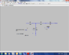
The datasheet says to bias it at 1.3V. My supply voltage is 5V and with a 100k bias resistor (i.e. between 5V and the mic +ve pin) it still sits at over 3V. Most other electret mics are biased with 1k to 10k ohm as they run higher than 1.3V. I know the FG series mic is different due to its size, but 100k seems a bit high. Is it best to increase the bias resistor or to use a voltage divider to deliver the 1.3V?

Mic max current draw is 50uA.

I've contacted Knowles for some more info (as the datasheet is very limited) but they're not responding.

For info this question is related to the following thread:

https://www.electro-tech-online.com/threads/lm386-instability-issue.139349/
 
Yes I think a divider would be best to keep the output impedance lower.
Maybe like this:
 

Attachments

  • bias.png
    bias.png
    141.2 KB · Views: 1,052
I should have mentioned - it's a 3 terminal mic. Positive, ground, and output.

ronv in your schematic you appear to have a voltage divider, 2.4k and 1k setting up a voltage of 1.5V, with a 6.8k bias resistor then in series with the mic. What is the purpose of the 6.8k? The device max current draw is 50uA which is 300 times smaller than the current draw of the voltage divider (1.5mA) so the divider voltage is stable. So why include the 6.8k? Also - this circuit is equally as applicable to a 3 terminal mic yes?

Mosaic, I've only scanned through their application notes so I must admit I hadn't looked at that one in any detail, however it does appear to be applicable only to 2 terminal mics?
 
DO NOT use the Applications Note for a 2-wires electret mic because your mic has THREE wires as shown on its connections sketch: Positive, Ground and Output. Also DO NOT use the wiring in post #2.

A 2-wires electret mic needs a 10k resistor to power it at about 0.5mA to its output pin. A 5V to 9V supply is used.

Your mic is powered directly from 1.3V to 1.6V without a resistor (or a voltage divider with a big electrolytic filter capacitor) and its output "might" need an external resistor to ground or just a series coupling capacitor.

Shame on Knowles for not showing a typical schematic.
 
Why would the circuit in post #2 not work?

I should also say that after a chaser email Knowles did respond and said:

Microphones are used with many different interface circuit types so we never made a recommended one, I am afraid.

The FG-23629-D65 will work with a supply voltage up to 3V. If your supply is 5V then you need to bring this down between 1.3 and 3V. The easiest way to do this is to use a voltage divider as described here:https://en.wikipedia.org/wiki/Voltage_divider. As noted on the datasheet the impedance of the microphone is 4400 Ohm.


So it can go up to 3V, so a 10k-10k voltage divider should do the trick at 2.5V. The large cap would short AC at the drain of the FET to ground yes? Would that not prevent AC current flowing through the FET?
 
Okay sorry I meant ignoring where the output is taken from in that circuit. So assuming I'm taking the output from the output terminal, would that circuit not be a suitable power supply network? I'm still unsure as to the purpose of R3 in that circuit?
 
Okay sorry I meant ignoring where the output is taken from in that circuit. So assuming I'm taking the output from the output terminal, would that circuit not be a suitable power supply network? I'm still unsure as to the purpose of R3 in that circuit?
Are you talking about the "bias" circuit posted by Ronv in post #2?
It is for a 2-wires electret mic that you do not have.
 
Yes. I know the circuit is for a 2 wire mic, but I'm asking why the circuit won't work for a 3 terminal mic. Ignoring the 'output' as labelled in that circuit, the only difference between it and a voltage divider as you've suggested is the resistor R3. So will the circuit not work because the common drain FET expects to see an AC ground at the drain, whereas in this circuit it sees R3?
 
R3 plus the source resistor inside the mic create a voltage divider for the DC and for the signal from the mic. Then the mic might not work.
 
Status
Not open for further replies.

Latest threads

New Articles From Microcontroller Tips

Back
Top