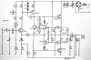
Hopefully I managed to get the circuit diagram up...
I am troubleshooting one of these amps and there are a few things I don't understand (I had trouble liek this last year).
My circuit right now contains all passive components and only T1.
I connected a sine input of about 1 V and I get a distorted waveform (clipped positive wave) on the collector of T1.
The base of T1 shows about 40V dc and the input voltage is 70V.
Why is there any clipping?
Uwe
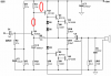