Continue to Site

Welcome to our site!

Electro Tech is an online community (with over 170,000 members) who enjoy talking about and building electronic circuits, projects and gadgets. To participate you need to register. Registration is free. Click here to register now.

  • Welcome to our site! Electro Tech is an online community (with over 170,000 members) who enjoy talking about and building electronic circuits, projects and gadgets. To participate you need to register. Registration is free. Click here to register now.

Best way to protect inputs?

Status
Not open for further replies.

Scarr

Member
Hi,

I want to protect some digital inputs going to a Atmega128, I don't really need opto-isolators but I do want some protection.

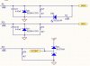
I have attached a schematic I found with protection but I'm not really sure if it's correct and why there is a difference?

Anyone help with an example?

P.S. It's for a automotive application so voltage range is 12v-30v and a possible high current supply.

Thx

Steve
 

Attachments

  • inputs.jpg
    inputs.jpg
    50.4 KB · Views: 1,375
Hi Scarr,
A 3V zener diode makes a lousy voltage regulator or voltage clamp.
On its datasheet, a BZX84-c3v0 has a max differential resistance of 95 ohms at 5mA (less for your higher current) while a half-decent BZX84-C6V2 has a max differential resistance of only 10 ohms at 5mA.

If the input voltage is 30V, more than 200mA will flow, much more than a little BZX can handle. Whatever amount its differential resistance is at more than 200mA, its voltage will certainly be much higher than only 3V.
 
Hi
In automotive designs First we try to limit the current through input port
The input ports of the microcontroller normally hav parasitic or intentionally developed diodes to VCC and GND at the inputs which are limited by current rating
So we try to keep the current below maximum even if the voltage is above rating
In our circuits we apply 16V through a series resistor directly (without any zener clamp) to the microcontroller
I dont know if your Atmega128 is a automotive grade processor or not so cannot say much about it.
Are you designing this circuit for commercial purpose?
 
I don't have any of my literature out to look up the diode types shown on the schematic provided, but the symbols drawn are for Schotty (hot carrier) diodes, not zener diodes. As such, in the first two circuits, they limit excursions of the signal to around -0.1 or -0.2 volts with no limit in the positive direction. In the second circuit, they clip the signal if it exceeds the window of -0.1/0.2v to +3.4/3.5v. Actual voltage depends upon the current through the diode, and for low currents on a hot carrier diode, the voltage drop will be quite low, around 0.1v

Dean
 
Thanks for the replies

First, Sorry for the dealy (been away) Also let me clarify the schematic was not mine, but borrowed :) just to try to understand how to protect inputs.

There are lots of helpfull comments, from what I can see is (and please correct me if I'm wrong) that simply using a larger series resistor will suffice?

How can I calculate the correct vaule for this resistor given that the voltage range is for automotive use (absolute min 6v - absolute max 40v)?

Thx Steve

P.S. Please feel free to comment on those voltages also :)
 
Found these little IC's

Hi,

Quick update, I found these little IC's (below) that can protect against over voltage, now if I add one of these to protect my inputs and as each PIN will only sinks 20ma I don't need the large resistor, is this correct?

https://www.electro-tech-online.com/custompdfs/2005/05/SP724.pdf


P.S. I am still looking at my outputs but it may be that I don't need any as it will be handeled via a RS232 and a Max2323

Thx again
 
First of all
Are you making this is a commercial product or just Hobbyist circuit?
If it is commercial then first confirm with microcontroller supplier is the ATMEGA128 is an automotive grade microcontroller?
 
Answers for instruite

Hi instruite,

It's the Atmega128L 8AI (-40c to 85c) now I'm not sure what defines an "Automotive grade" MCU appart from the temperature (this one is classed as industrial) so I can't really answer your question. if you can tell me what you looking for I can see if it fits the criteria.

It is hobbyist but I do want to make it commercial (hopefully) so I want whatever you would recommend for comercial use.

Thx

P.S. Just noticed in the app notes next to the Atmega128L 8AC that runs from -0c to 70c, this IC it is classed as comercial (C for comercial I for Industrial) so I think it's safe to say it's of comercial grade, still not sure about automotive :?

Steve
 
Hi Scarr,
Well automotive ICs are normally range from -40C to +125C/150C.
You need the ICs temperature range to be more than the ambient maximum temperature because of the self heat dissipation in the circuit (normally due to driver and power supply ICs).
If you check the sites of freescale, renesas you will see that those manufcaturers have different category for automotive and industrial classes.
What exactly are you trying to make? If you can tell me that I may be able to help you more.
 
More info

It's just a in-car monitoring system, I want ot be able to monitor anything I feel like (with add on modules) but I do want three standard digital inputs.

Thx

P.S. Do you think this MCU will be OK then keeping in minf it's max temp is +85C?
 
If you donot plan to integrate any device which cause high power dissipation like motor drivers or solenoid drivers and you plan to keep your module in the place in the car where ambient temperature will be less than 65C then you can use an IC with max operating temperature of 85C
If you really plan to develop this as commercial product I will recommend you to find an IC with max rating around 125C
For hobby purpose I think it should not create any problem.
 
OK apart from temp...

So back to the question of just putting a large resistor, will this work and if so whats the way to calculate it?

Thx
 
Re: OK apart from temp...

Scarr said:
So back to the question of just putting a large resistor, will this work and if so whats the way to calculate it?

Assuming Atmel have diodes to Vdd and Vss like a PIC?, a resistor should be all you need - no need to calculate anyhting really, stick a 100K in place!.

If you want to work out the minimum value it can be, then check the spec for the protection diodes on the datasheet - this will give their maximum forward current. Calculate the voltage drop across the resistor, apply ohms law, and you have the minimum value. But 100K is going to be greatly higher than the minimum, and should be no problem as it will limit current to well below permissable levels.
 
Hi
To calculate the value of resistor you normally need the maximum current rating of the input terminal which in most cases is not normally specified in the datasheet.
So you will have to contact the manufacturer for the same.
The value of resistor
Minimum - Maximum VB / maximum current rating
Maximu - Leakage current * Max resistance < Vil max (maximum low level input detection voltage )
 
Status
Not open for further replies.

Latest threads

New Articles From Microcontroller Tips

Back
Top