Continue to Site

Welcome to our site!

Electro Tech is an online community (with over 170,000 members) who enjoy talking about and building electronic circuits, projects and gadgets. To participate you need to register. Registration is free. Click here to register now.

  • Welcome to our site! Electro Tech is an online community (with over 170,000 members) who enjoy talking about and building electronic circuits, projects and gadgets. To participate you need to register. Registration is free. Click here to register now.

Best way to invert this voltage?

Status
Not open for further replies.
No.
When the left side of the signal goes negative it hangs up on the bottom diode and will not go negative. So the right side pushes up and charges the bottom cap. Next then the left side goes positive it pushes up and charges the top cap. In one cycle you will have the peak voltage on each cap and they add to make P-P voltage.
1537561244655-png.114623

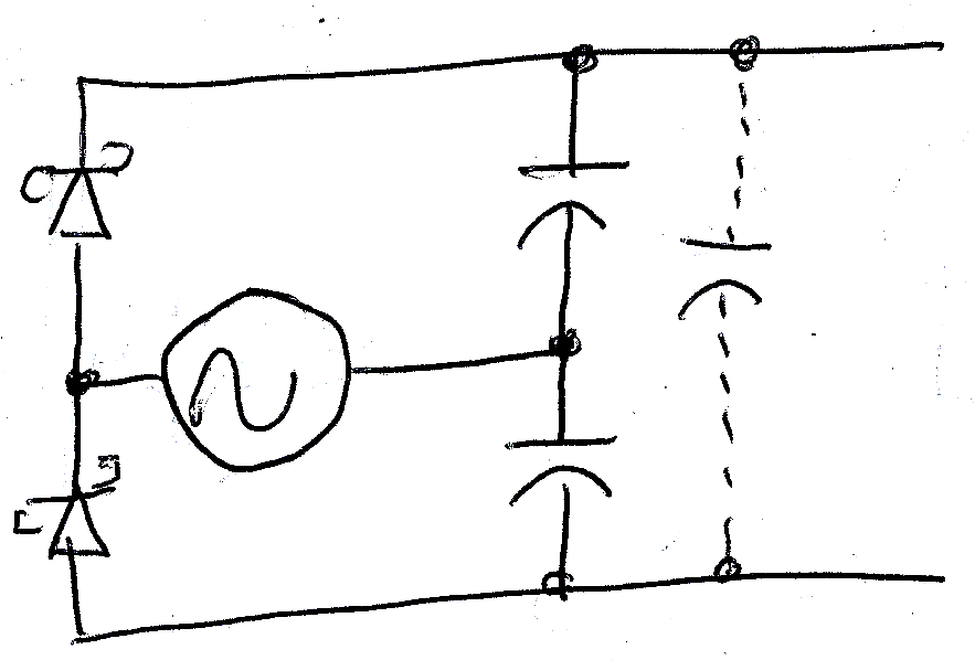
Doesn't this assume the cap is not charged on it's cycle? Once it is the power will go through the load and through
No.
When the left side of the signal goes negative it hangs up on the bottom diode and will not go negative. So the right side pushes up and charges the bottom cap. Next then the left side goes positive it pushes up and charges the top cap. In one cycle you will have the peak voltage on each cap and they add to make P-P voltage.
1537561244655-png.114623

LTSpice shows this as otherwise, if there's a significant load. Say the right side is positive, the upper cap charges and power goes through the load and up through the bottom capacitor.
 
I don't understand your comment.
If you look at the top half of the circuit it is clearly a half wave power supply. Signal, diode cap.
If you look at the bottom half of the circuit it is a half wave power supply, with the diode pointing in the reverse direction. (negative supply)
Stack two supplies on top of each other and you get 2x the voltage.

Things might seem strange on the first cycle but it does work.

It might help to think of "ground" as being the between the two capacitors. Now you have a positive supply and a negative supply. You can call "ground" any point you want.
 
It's frequency/load dependant.

Example: as the top cap is charged the power will go through the load and back through the bottom capacitor. The hope is the capacitor won't have charged before the AC switches cycle. If you put it in LTspice and do a frequency sweep with a load (I used F = V*2 and 5ohm load) you can see the current going through the bottom cap.
 
Red lines show discharge current flowing from cap(s) to load.
Green lines shows charging current for first half of cycle.
Blue lines shows charging current for second half of cycle.
1537907375401.png

The two caps charge 1/2 wave.
The single cap charges full wave. (or charges twice per cycle)
 
And what is wrong with that?
During that time the top cap is charging while the bottom cap is discharging.
>The charge is the full current of the source - load current.
>The discharge is only the load current.
 
In my simulation it had discharged, the top had charged and the bottom was in short. Too much load, not enough capacitance, something like that.
 
If you are concerned about the caps being reverse polarised at extremely low frequencies or while starting up, add reverse polarity schottky diodes across them.

They will have no effect on normal operation.
 
Status
Not open for further replies.

Latest threads

New Articles From Microcontroller Tips

Back
Top